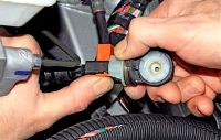
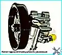
The Renault Duster starter is a four-pole, four-brush DC motor with permanent magnet excitation, combined with an electromagnetic two-winding traction relay
The covers and the stator housing are tightened with two bolts. Permanent magnets are fixed in the stator housing.
The rotation from the armature shaft of the electric motor is transmitted to the drive gear through the freewheel.
When the key in the ignition switch is turned to position “D” (engine start), the voltage from the battery is applied to the retracting and holding windings of the traction relay, as a result, the drive lever moves and the starter gear engages with the toothed rim of the engine flywheel.
At the same time, the armature of the traction relay closes the power contacts (at this moment, the retractor winding is turned off) and voltage is supplied to the starter motor from the battery.
The starter armature rotates the engine crankshaft through the freewheel.
After starting the engine, when the speed of the gear exceeds the speed of the starter shaft, the freewheel will unlock and slip, protecting the starter from high speed and damage.
Removing and checking the K4M engine starter
Preparing the car for work.
We install the car on a viewing ditch or a lift.
Disconnect the negative battery terminal.
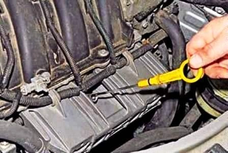
Remove dipstick
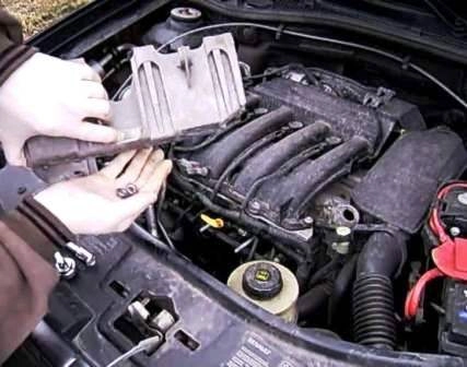
Removing the fuel rail protection
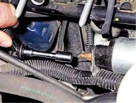
Unscrew the nut with a 10 head
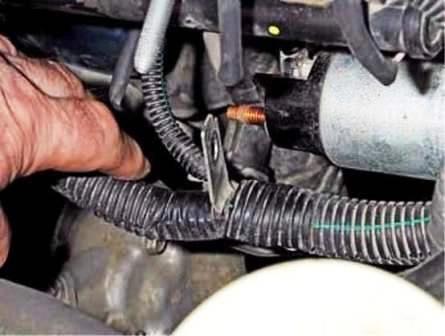
Remove the wire tip from the contact bolt of the traction relay
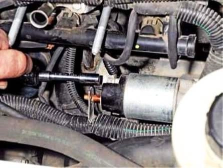
Unscrew the nut with an 8 head
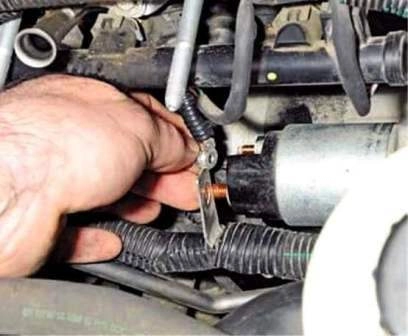
Remove the wire tip from the control output of the traction relay
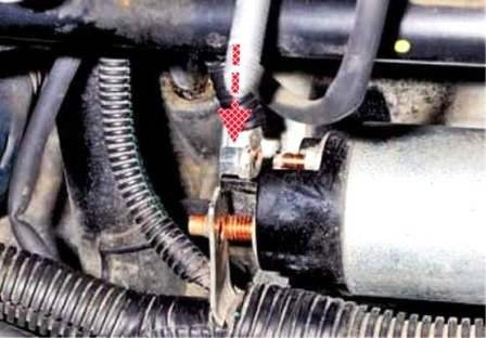
The nut is fixed on the end of the wire
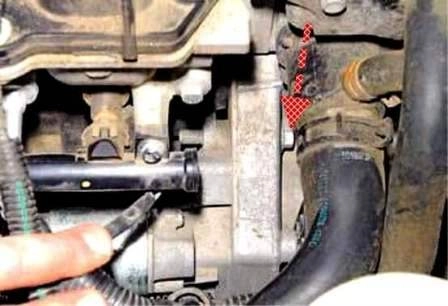
With a head of 13, unscrew the upper starter mounting bolt
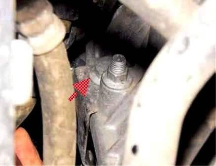
Unscrew the lower starter mounting bolt (shown from the bottom of the car).
This bolt also secures the harness holder bracket
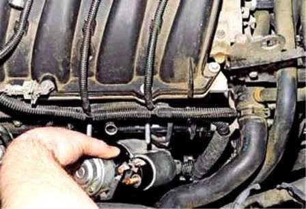
Remove the starter
Checking the starter drive
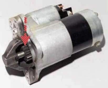
Turn the drive gear with a screwdriver.
The gear must turn in one direction with the drive shaft, and in the other direction on the shaft when water. Otherwise, the drive must be replaced.
Use a screwdriver to move the drive gear along the shaft.
The gear should move easily along the shaft without jamming.
To check the starter, we connect the wires: the positive terminal of the battery with the upper contact bolt 1 of the traction relay, and the negative terminal with the starter housing.
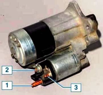
Use a screwdriver to bridge the upper contact bolt 1 and control output 3 of the traction relay.
This should extend the drive gear and engage the starter motor.
Otherwise, we check the electric motor and the starter traction relay.
To check the electric motor, we connect the positive terminal of the battery to the lower contact bolt 2 of the traction relay, and the negative terminal to the starter housing.
In this case, the motor shaft must rotate.
Otherwise, the motor is defective.
To check the traction relay, we connect the positive terminal of the battery with the control terminal 3 of the traction relay, and the negative terminal to the starter housing.
The drive gear should pop out.
If this does not happen, the traction relay is faulty.
Install the starter in reverse order.
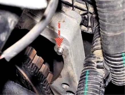
The dowel pin on the clutch housing must fit into the appropriate hole in the starter front cover.
Removing and checking the engine starter F4R
Disconnect the negative battery terminal.
Removing the protection of the power unit (article - Removing the protection of the engine, fenders and mudguards)
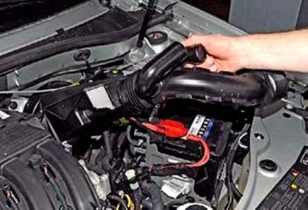
Remove the air intake with the resonator assembly
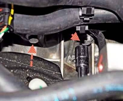
With a 13 head, unscrew the two starter mounting bolts
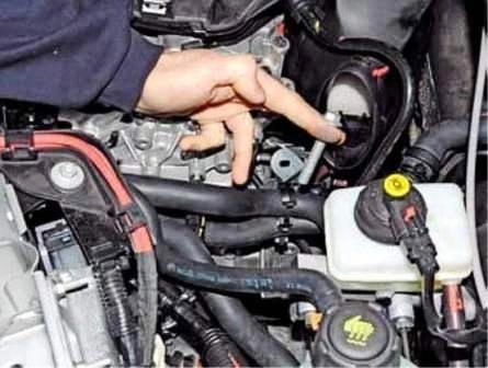
Removing the bolts
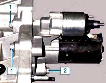
Bolt locations
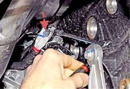
With a head of 8, unscrew the nut that secures the wire tip to the control output of the traction relay.
The nut is fixed on the end of the wire
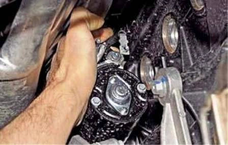
Remove the wire end from the relay output
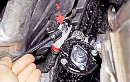
With a head of 10, unscrew the nut securing the wire tip,
connected to the positive terminal of the battery.
The nut is fixed on the end of the wire
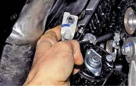
Remove the wire tip from the contact bolt of the traction relay
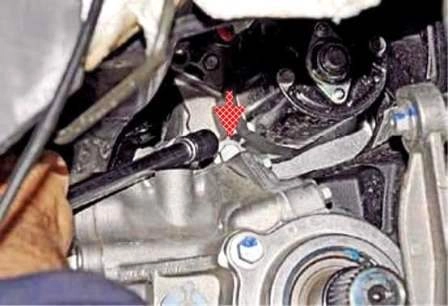
With a 13 head, unscrew the lower starter mounting bolt
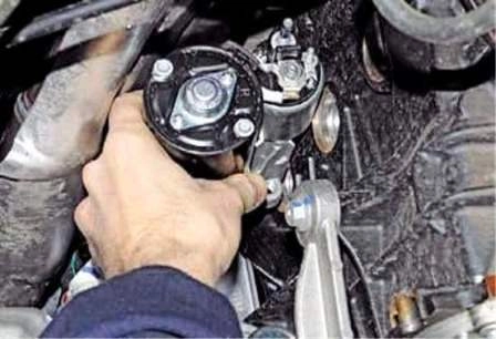
Remove the starter
Checking the starter drive
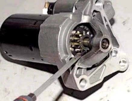
Turn the starter drive gear with a screwdriver.
The gear must rotate in one direction with the drive shaft, and in the other direction on the drive shaft.
Otherwise, the drive must be replaced.
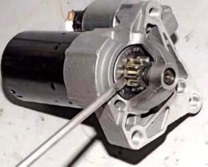
Use a screwdriver to move the gear along the shaft.
The gear should move easily along the shaft without jamming.
If the gear sticks on the shaft, the drive needs to be replaced.
To check the starter, we connect with wires: the positive terminal of the battery with the upper contact bolt of the traction relay, and the negative terminal with the starter housing.
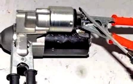
Use a screwdriver to bridge the upper contact bolt and the control output of the traction relay.
This should extend the drive gear and engage the starter motor.
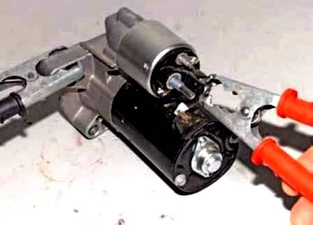
To check the electric motor, we connect the positive terminal of the battery to the lower contact bolt of the traction relay, and the negative terminal to the starter housing.
In this case, the motor shaft must rotate. If this does not happen, the electric motor is faulty.
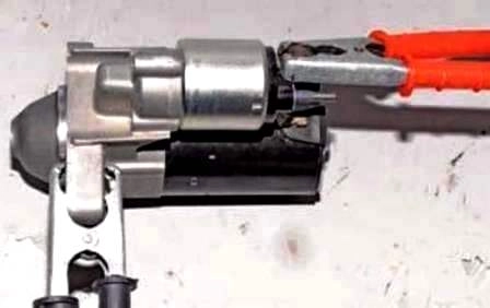
To check the traction relay, we connect the positive wire of the battery to the control output of the traction relay, and the negative terminal to the housing.
The drive gear should pop out.
If this does not happen, the traction relay is faulty.
When installing the starter, first we put the wire ends on the contact bolt and the control output of the traction relay and screw on the nuts for their fastening.
We install the starter in place and bait the three bolts of its fastening.
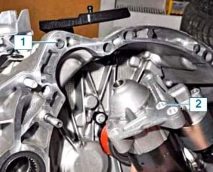
Installation sleeve 1 in the clutch housing must fit into hole 2 of the starter front cover.
After that, we finally tighten the starter mounting bolts and the wire end nuts.
Install all parts in reverse order.
Starter disassembly
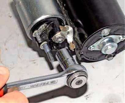
Unscrew the nut with a 13 head
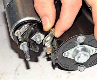
Remove the tip of the wire from the output of the traction relay
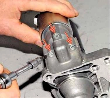
Using a TorxT-25 wrench, unscrew the three screws securing the traction relay
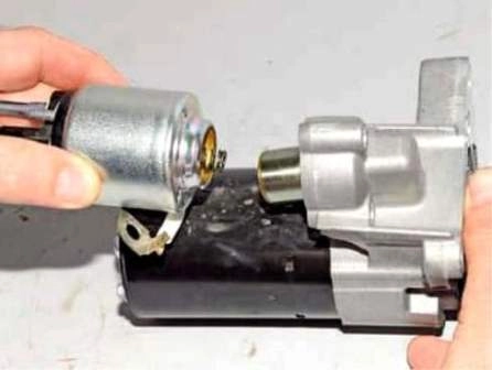
Remove the traction relay
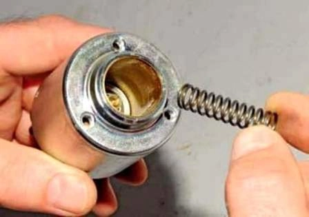
Remove the spring from the traction relay
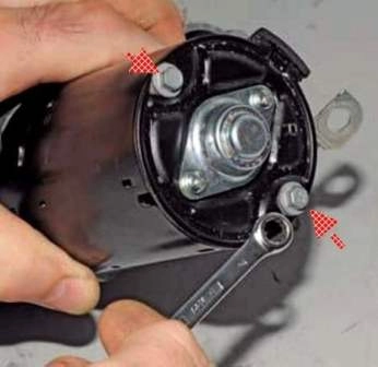
Unscrew the two tie bolts with a 7 spanner
Disconnecting the front cover and starter housing
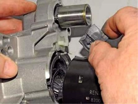
Remove the seal
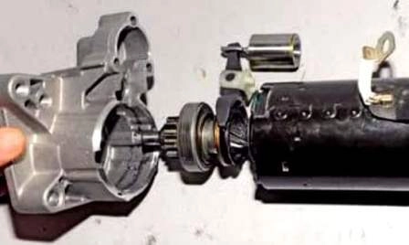
Remove the front cover
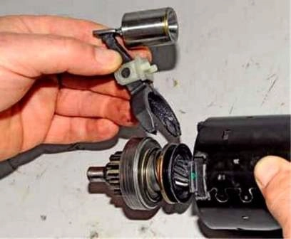
Remove the drive lever
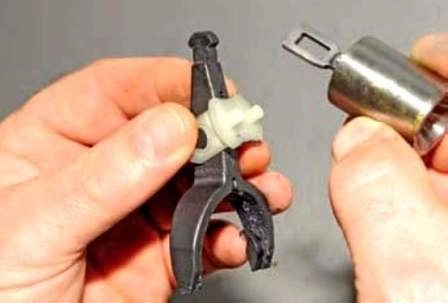
Remove the anchor of the traction relay from the drive lever
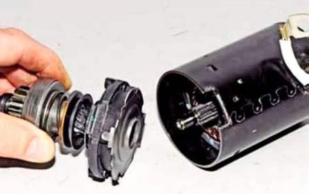
Remove the drive assembly
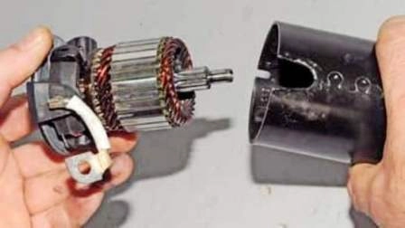
Remove the anchor with the brush holder from the starter housing
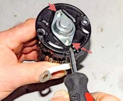
Use a Phillips screwdriver to unscrew the two screws
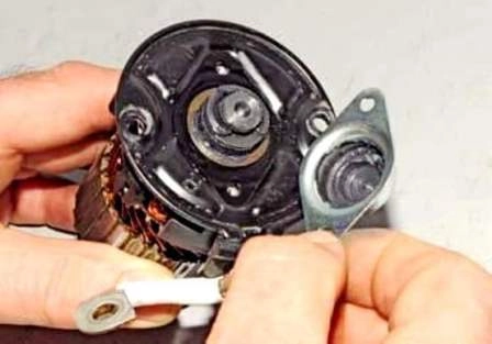
Remove the cover
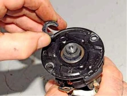
Remove the lock washer from the groove of the armature shaft
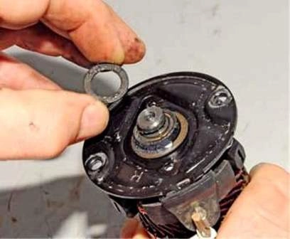
Remove the spacer
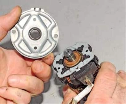
Remove the back cover
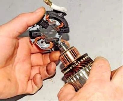
Remove the brush holder
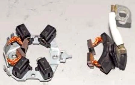
Remove the insulated brushes from the brush holder
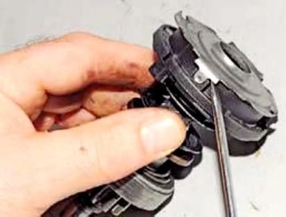
Pry off the cover with a screwdriver
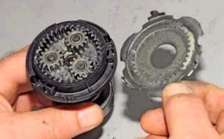
Remove the planetary gear cover
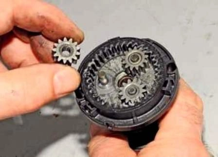
Removing the three satellites of the planetary gear
We rest the end surface of the ring gear on a wooden block.
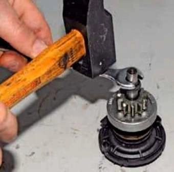
Having placed the jaws of the open-end wrench at 12 on the restrictive ring of the drive gear travel and, having hit the key with a hammer, we press the restrictive ring.
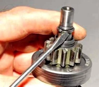
Pry off with a screwdriver
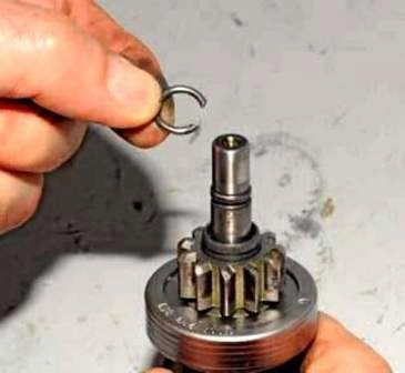
Remove the locking ring
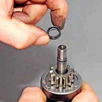
Remove the restrictive ring
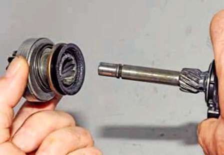
Remove the overrunning clutch with drive gear assembly
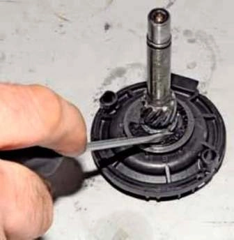
Screw off the groove with a screwdriver
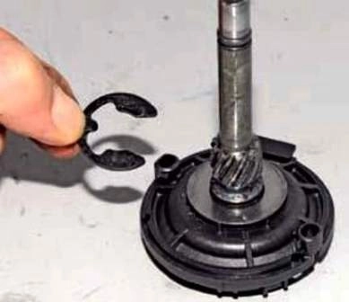
And remove the retaining ring
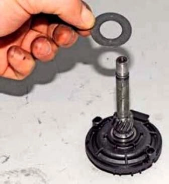
Slide the washer off the drive shaft
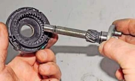
And the planetary ring gear
We inspect and check the condition of the collector and armature windings.
Charring of windings is not allowed.
The ends of the windings must be well soldered to the collector lamellas.
If the collector is slightly burned, we clean its plates with fine abrasive sandpaper.
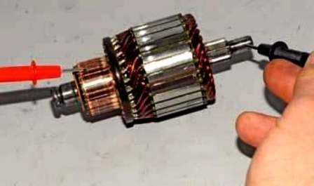
Using an ohmmeter, we check the short circuit of the armature winding to ground.
The resistance should be very high (tend to infinity).
Replace a broken anchor.
We inspect the brushes, they should not have cracks and chips. Otherwise, replace the brush holder with a new one.
We assemble the starter in reverse order.
We mount the brush holder before installing the anchor in the starter housing.
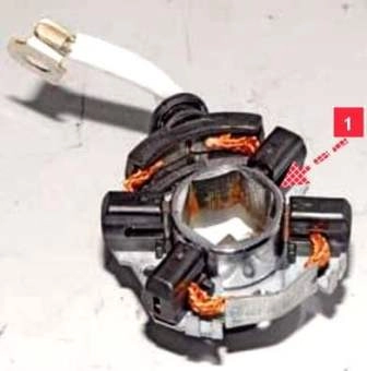
Before installing the brush holder on the armature collector, we sink the brushes into the guides and insert mandrel 1 into the central hole of the brush holder.
A tool head with an outer diameter of 30.5 mm can be used.
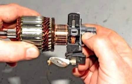
Pressing the mandrel to the collector, we shift the brush holder from it to the collector.
We install the back cover, spacer and lock washers and close them with a cover.
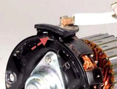
Set the rear cover so that the protruding part of the cover is aligned with the rubber seal of the brush leads.
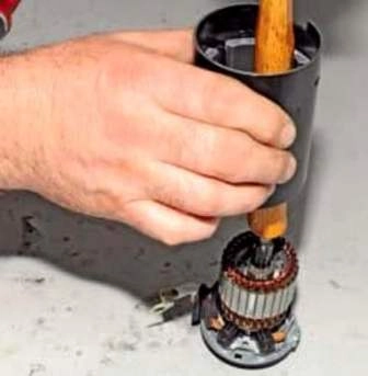
When installing the starter housing on the anchor, hold the armature with the hammer handle from attracting it with permanent stator magnets and lower the housing onto the back cover.


