


We replace the gasket under the cylinder head during engine repair or when gas or coolant leaks through the gasket.
To carry out the work, the following tools are required: 10, 16, 18 mm sockets, Torx E14, 13 mm spanner, screwdrivers, TDC setting tool, camshaft locking tool, torque wrench, pliers.
We prepare the vehicle for the task.
We depressurise the fuel system (described in the article “Replacing the additional fuel filter”).
We disconnect the negative battery terminal.
We drain the engine coolant (article – Checking and replacing the engine coolant).
We remove the timing belt (article – Checking and replacing the timing belt).
We disconnect the downpipe from the exhaust manifold (article – Removing exhaust system components).
We disconnect the wiring connectors:
- – from the injectors;
- – from the throttle position, absolute pressure, coolant temperature, intake air temperature and oxygen concentration sensors;
- – from the idle speed control valve;
- – from the ignition coils.
We remove the air filter (Removing and installing the air intake and resonator).
We take the engine wiring harness out of the holders on the engine and move it aside.
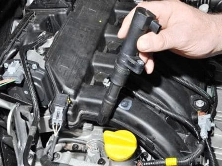
We remove the ignition coils (article – Replacing ignition coils and spark plugs).
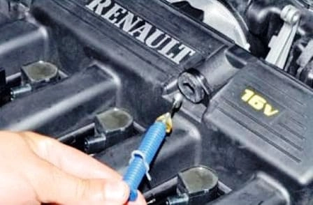
On the K4M engine, we disconnect the cable from the throttle assembly.
We take the cable out of the bracket on the intake pipe resonator and move it aside.
We disconnect the canister purge hose from the intake pipe.
We disconnect the fuel line from the fuel rail.
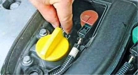
On the F4R engine, we press the retainer of the phase regulator valve wiring connector.
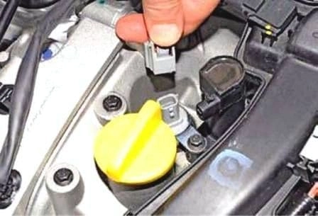
We disconnect the connector from the phase regulator valve.
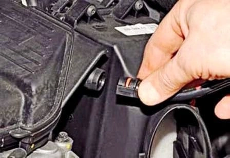
We disconnect the hose to the brake servo from the intake pipe, squeezing its retainers.
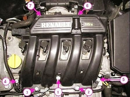
We unscrew the seven bolts securing the intake pipe to the cylinder head cover.
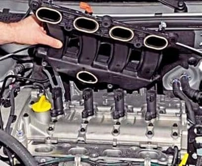
We remove the resonator.
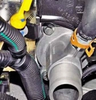
We loosen the clamps securing the two hoses by squeezing the bent tabs with pliers, and slide the clamps along the hoses.
We disconnect the hoses from the thermostat unions.
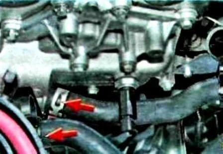
We disconnect the hoses from the cylinder head.
We unscrew the bolts securing the power steering pump and move the pump aside.
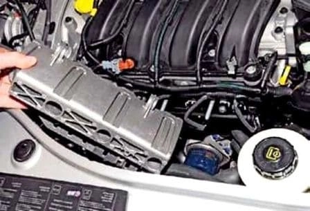
We remove the fuel rail guard.
We remove the cylinder head cover (article – Removing the cylinder head cover).
We remove the camshafts.
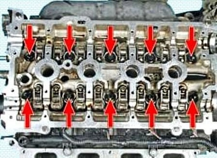
Using a Torx E14 socket, we unscrew the ten bolts securing the cylinder head and take out the bolts.
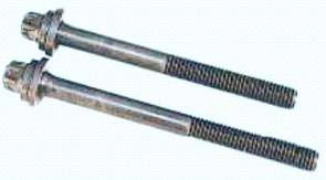
The cylinder head mounting bolts must be replaced with new ones.
The cylinder head mounting bolts are of different lengths.
When removing, the position of the bolts must be remembered.
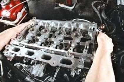
We remove the cylinder head (it is better to do this with two people).
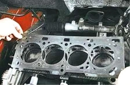
We remove the gasket.
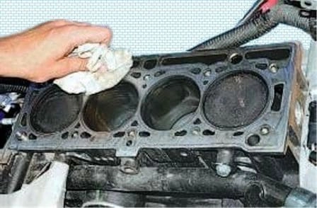
We clean the surfaces of the cylinder head and block.
We check the cylinder head for warping.
To do this, we place a straight edge on the cylinder head surface first in the middle lengthways, then crossways and diagonally, and measure the gap between the cylinder head surface and the straight edge with a feeler gauge.
We replace the cylinder head if the gap is more than 0.05 mm.
We install the cylinder head in the reverse order.
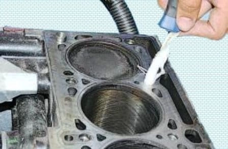
We remove oil or coolant that entered the threaded holes for the cylinder head bolts during removal of the cylinder head.
We install a new gasket.
We replace the bolts with new ones.
Before screwing in the bolts, we lubricate the threads with engine oil.
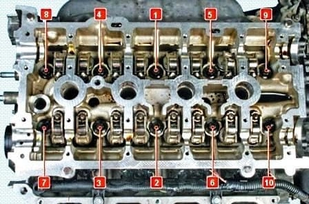
We tighten the bolts on a cold engine, in the order shown in the figure, in two stages:
- – first stage (preliminary) – tighten the bolts to 20 Nm;
- – second stage – turn the bolts through an angle of 240±5°.
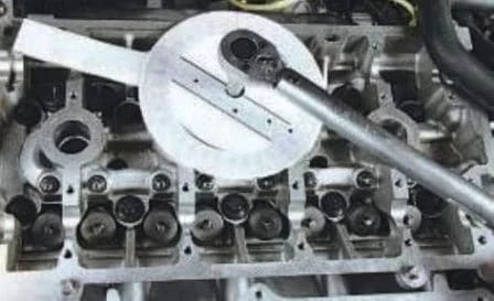
The photo shows an example of turning a cylinder head bolt through a certain angle.
We install all parts in the reverse order.
When installing the resonator, we tighten the mounting bolts in the sequence shown in the figure to 9 Nm.


