


The front suspension is independent, of the MacPherson strut type with an arm and spring arrangement, with telescopic shock absorber struts, coil springs, transverse arms, and an anti-roll bar of the torsion type.
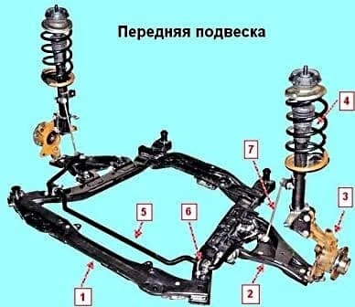
The main elements of the front suspension are the telescopic shock absorber struts, which combine the functions of a telescopic element of the guide mechanism and a damping element for the vertical oscillations of the wheel relative to the body.
On the shock absorber struts are assembled coil springs, compression buffers with protective covers and upper mounts with thrust bearings.
Through the upper mount the load is transmitted to the car body.
The shock absorber strut is connected to the suspension arm through the steering knuckle by a ball joint.
The anti-roll bar is connected to the subframe of the front suspension by two clamps through rubber bushes, and to the shock absorber struts — by anti-roll bar links.
The suspension arms are attached to the subframe of the front suspension through rubber-metal joints.
The front wheel hubs are installed on non-adjustable double-row angular contact ball bearings.
We examined the removal of the subframe in the article — Removing the subframe of the car.
The replacement of the front wheel hub bearing is examined in the article — Replacing the front wheel hub bearing.
Let us examine the replacement of the remaining suspension components.
Removing the anti-roll bar link
We remove the anti-roll bar link for replacement in the event of deformation of its rod, the appearance of play in its ball joints, damage to the protective covers of the joints, and during the repair of other suspension elements.
We carry out the work on a level surface.
We jack up the front part of the car — both front wheels, since when jacking up only one wheel the anti-roll bar presses the suspension elements upwards, which hinders dismantling.
We remove the wheel.
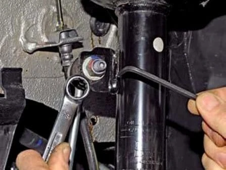
With a 16 mm spanner we unscrew the nut securing the pin of the upper joint of the anti-roll bar link, holding it against turning with a 5 mm hex key.
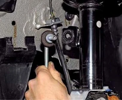
We bring the pin out of the opening of the shock absorber strut bracket.
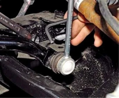
In the same way we unscrew the nut securing the pin of the lower joint of the link to the anti-roll bar.
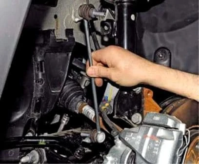
We remove the anti-roll bar link.
We install the link in the reverse order. We tighten the nuts securing the pins of the anti-roll bar link to a torque of — 35 N·m.
Replacing the anti-roll bar bushes
We replace the rubber bushes securing the anti-roll bar to the subframe of the front suspension in the event of their ruptures and significant wear, as a result of which play arises in the connection of the parts.
We carry out the work on a level surface.
We jack up the front part of the car — both front wheels, since when jacking up only one wheel the anti-roll bar presses the suspension elements upwards, which hinders dismantling.
The work is shown on the left anti-roll bar bush, the right bush is removed similarly.
We remove the wheel.
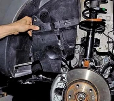
We remove the dirt shield of the engine compartment (article — Removing the engine guard, wheel arch liners and mudflaps).
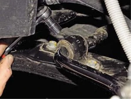
With a 13 mm socket we unscrew two bolts securing the anti-roll bar clamp to the subframe.
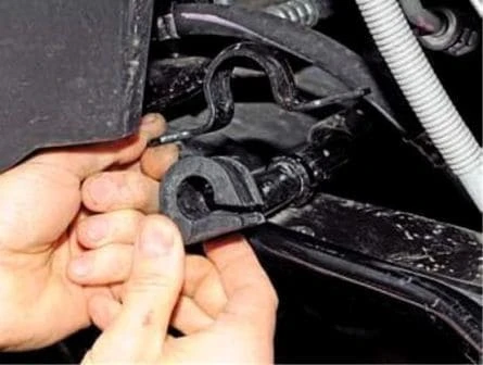
We remove the clamp and bush of the anti-roll bar.
We install the bush and clamp of the anti-roll bar in the reverse order.
When installing, it should be taken into account that the slot on the bush must be directed forwards (in the direction of travel of the car).
We tighten the bolts securing the clamp to a torque of — 25 N·m.
Removing the anti-roll bar
We remove the anti-roll bar for replacement in the event of its deformation or breakage.
We carry out the work on an inspection pit or a trestle.
We disconnect the anti-roll bar links from the bar and remove the bar bushes, as described above.
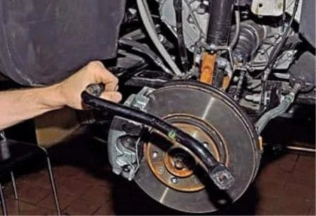
We bring the bar out to the side.
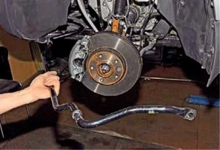
We take out the bar.
We install the bar in the reverse order.
Removing and dismantling the shock absorber strut
We remove and dismantle the shock absorber strut when it is necessary to replace its spring, upper mount, mount bearing, compression buffer with protective cover or shock absorber.
We remove the shock absorber strut on a level surface.
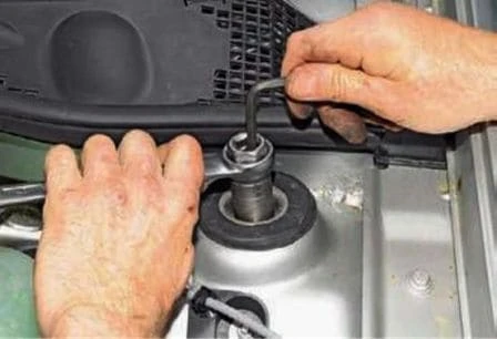
We open the bonnet and with a deep 21 mm socket with an outer hexagon (or, having gripped the outer surface of the socket with a tubular spanner) we loosen the tightening of the nut of the upper attachment of the shock absorber strut, holding the shock absorber rod against turning with a 6 mm hex key.
We remove the wheel and fix the car on a stand.
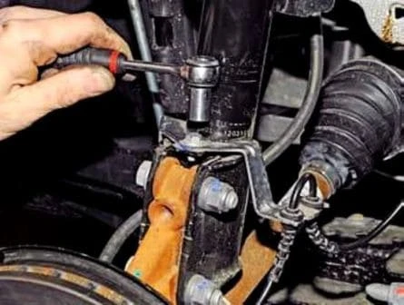
With a 10 mm socket we unscrew the bolt securing the holder of the wires of the wheel speed sensor.
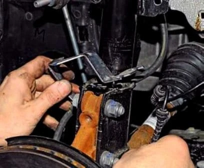
We move the holder with the wiring harness away from the strut.
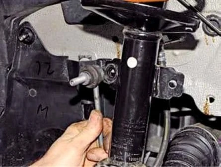
We disconnect from the shock absorber strut bracket the anti-roll bar link, as described above.
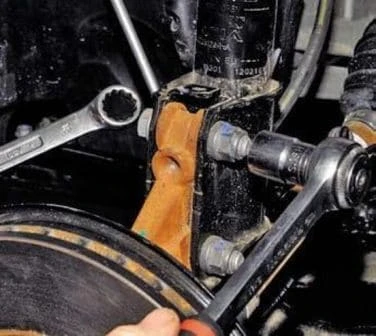
With an 18 mm socket we unscrew the nut of the bolt of the upper attachment of the strut to the steering knuckle, holding the bolt against turning.
We also unscrew the nut of the bolt of the lower attachment of the strut. We take out the bolts or knock them out with a drift.
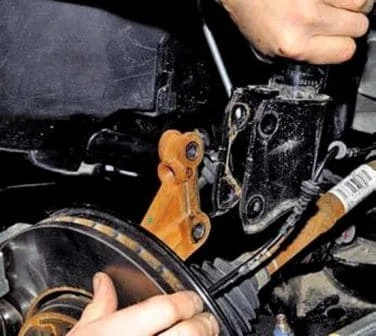
We move the strut away from the steering knuckle.

Holding the strut against falling, we finally unscrew the nut of its upper attachment.
We remove the shock absorber strut.
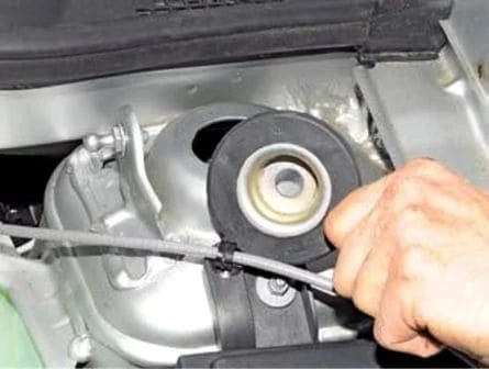
We remove the rubber-metal support washer of the upper attachment of the shock absorber strut.
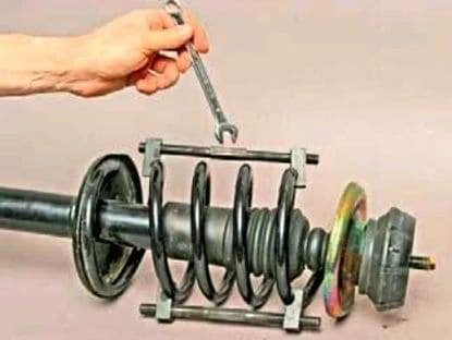
We compress the spring with compressors.
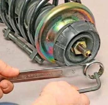
Having compressed the spring, with a ring spanner 27 we unscrew the nut securing the upper mount, holding the rod with a 6 mm hex key.
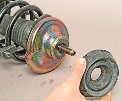
We remove the strut mount.
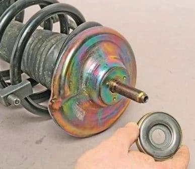
We remove the bearing of the upper mount.
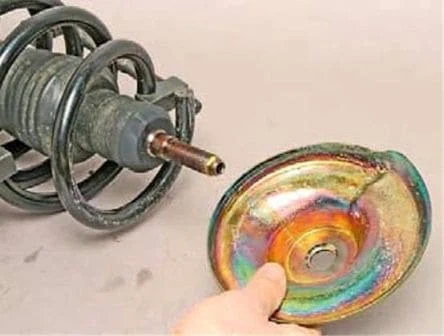
We remove the upper spring cup.
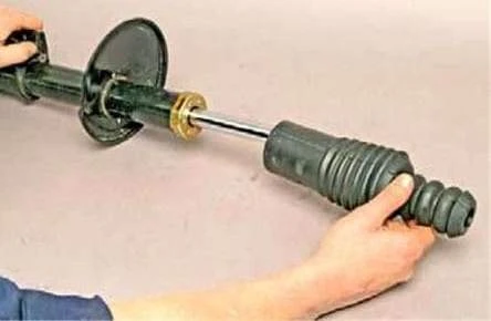
We remove the compression buffer with protective cover.
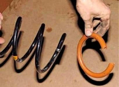
We remove the spring cover.
We assemble and install the shock absorber strut in the reverse order.
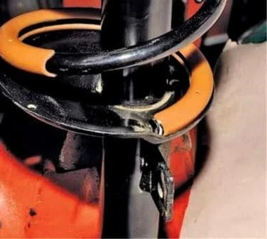
We install the spring so that its lower coil rests against the protrusion of the lower spring cup welded to the strut body.
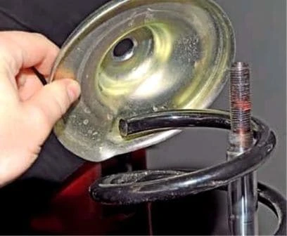
And so that the upper coil rests against the stamping of the upper spring cup.
We tighten the nut securing the upper mount to a torque of — 62 N·m.
Removing the arm and the ball joint
We remove the arm for replacement of the ball joint or the arm itself in the event of its deformation, the presence of cracks in the metal, as well as in the event of damage (rupture, peeling of the rubber) of the arm rubber bushes.
We carry out the work on an inspection pit or a trestle.
We jack up the front part of the car — both front wheels, since when jacking up only one wheel the anti-roll bar hinders the dismantling of the arm, pressing the suspension elements upwards.
We remove the front wheel.
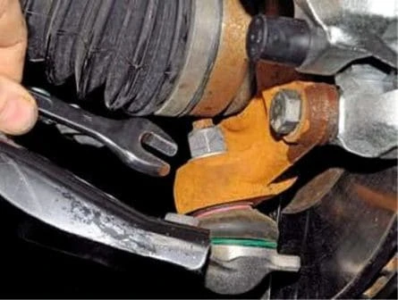
With an 18 mm spanner we unscrew the nut securing the pin of the ball joint until it rests against the body of the outer joint of the wheel drive.
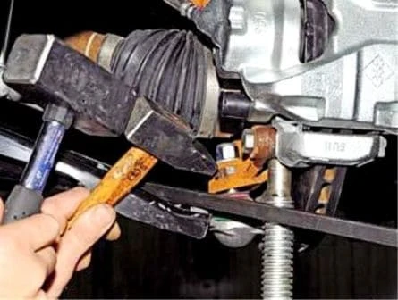
We place an adjustable stop under the steering knuckle.
With a mounting spatula we press the arm with the ball joint downwards, at the same time striking with a hammer through a spacer on the eye of the steering knuckle, pressing the pin of the ball joint out of the eye.
Then, as the pin of the ball joint comes out of the eye of the steering knuckle, we unscrew the nut.
We bring the pin of the ball joint out of the opening of the steering knuckle.
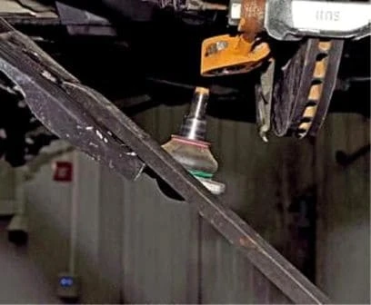
With a ring spanner 21 we unscrew the nut of the bolt of the front attachment of the arm, holding the bolt with a 21 mm socket.
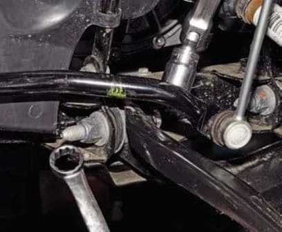
We take out the bolt or knock it out with a mandrel.
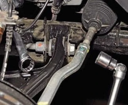
We also unscrew the nut of the bolt of the rear attachment of the arm and take out the bolt.
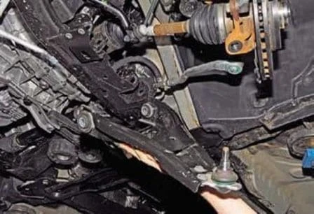
We remove the suspension arm.
We install the arm in the reverse order.
We finally tighten the nuts of the bolts securing the arm to the subframe to a torque of — 62 N·m.
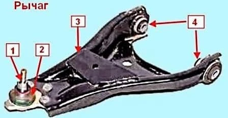
The ball joint is not supplied separately by the manufacturer as a spare part and is replaced together with the arm.
However, it can be removed from the arm and replaced with a similar joint from other manufacturers.
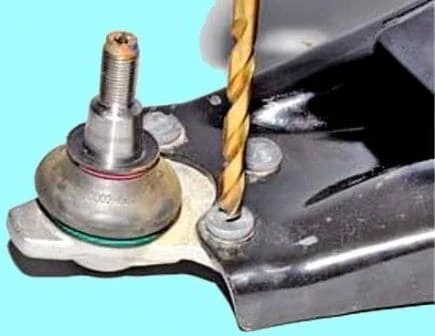
To do this, we drill out the heads of the rivets securing the ball joint body and secure it with bolts and nuts.


