We remove the power plant supports when dismantling the power plant components, as well as when replacing the supports themselves.
A characteristic defect of the supports is the delamination of the rubber layer, in which knocks appear when starting the engine, as well as when driving over bumps.
We show the removal of supports using the F4R engine as an example.
The right K4M engine mount is slightly different in shape but has the same attachment points.
Replacing the rear support
We perform work on a lift or a viewing ditch
Removing the engine crankcase protection (article - Removing the engine protection, wheel arch liners and mudguards Renault Duster)
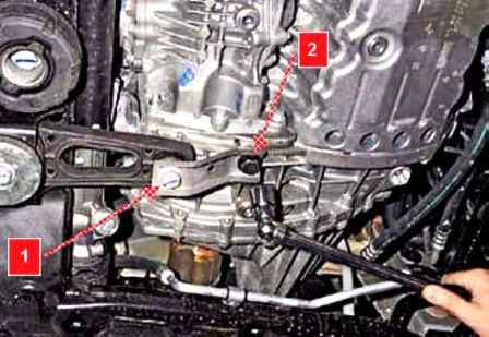
Using a 21 head, unscrew bolt 1 and loosen bolt 2 securing the support to the gearbox
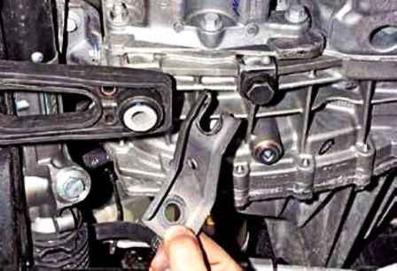
Remove the support bracket
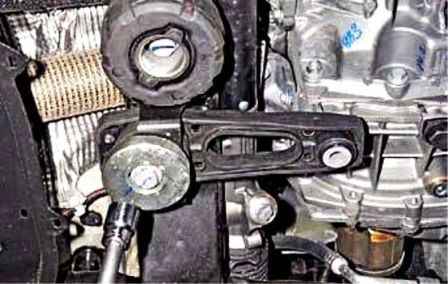
Using a 21 head, unscrew the bolt securing the anti-vibration washer and support to the front suspension subframe
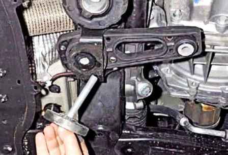
Remove the bolt with washer
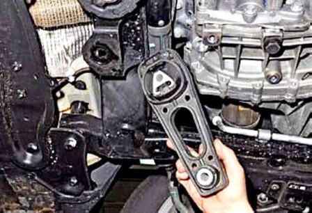
Remove the support
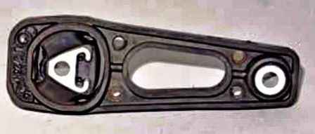
Install the rear support in reverse order
Replacing the right support of the power plant
We substitute a jack under the engine sump through a wooden block.
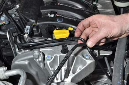
We remove from the holders the tube for supplying fuel to the rail and supplying fuel vapor to the receiver
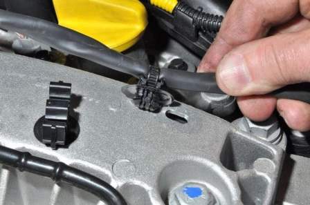
Remove the wire harness holder from the support bracket hole
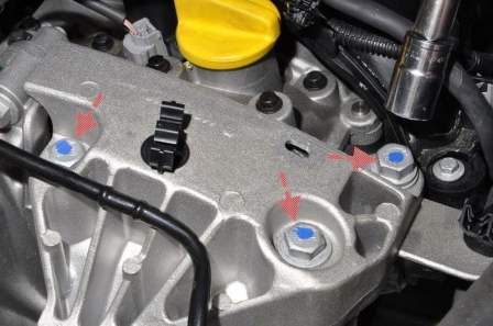
With a 16 head, unscrew the three bolts securing the support bracket to the top cover of the timing drive
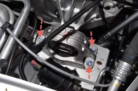
We unscrew the three bolts securing the support to the body
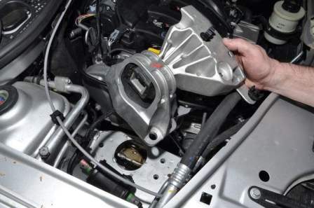
Remove the right support of the power plant
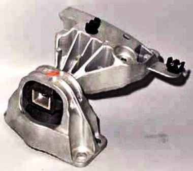
Replacing the left support of the power plant
We substitute a jack under the gearbox housing through a wooden block
Remove the battery
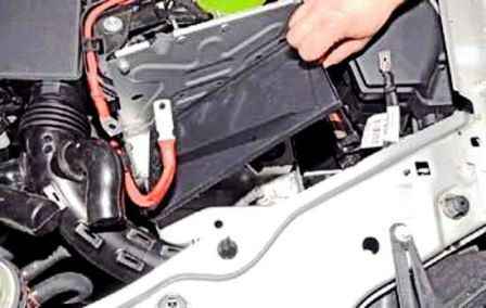
Remove the plastic battery tray.
We unscrew the two nuts securing the expansion engine cooling reservoir.
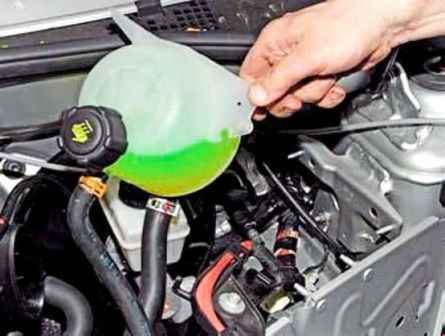
Remove the tank from the studs of the body bracket and move the tank on the hoses to the side
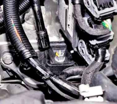
With a 16-head, unscrew the nut of the stud securing the support to the gearbox bracket
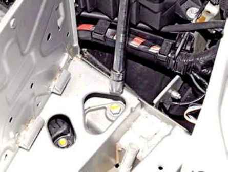
We unscrew the bolt of the upper fastening of the support bracket to the left side member
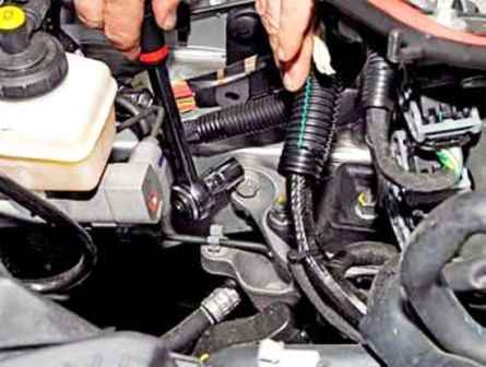
With a 16 head, unscrew the bolt of the rear fastening of the support bracket to the side member
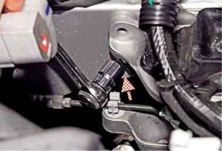
Loosen the rear bolt of the lower mounting of the bracket to the side member by a few turns
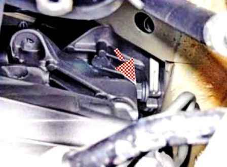
Loosen the front bolt of the lower support bracket to the side member by a few turns
We slightly lower the power unit so that the pin of the gearbox bracket comes out of the hole in the support cushion.
Raise the support so that the slots in the lower part of its bracket come off the rods of the two lower mounting bolts
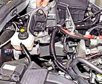
Remove the left support with the bracket assembly from the engine compartment
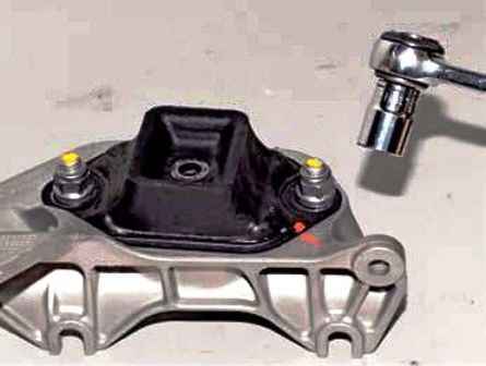
With an 18 head, unscrew the nut of the bolt securing the support to the bracket
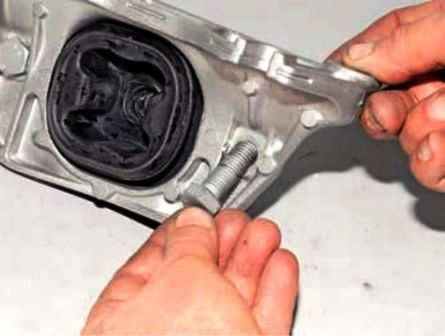
Remove the bolt. We also unscrew the nut of the other bolt and remove the bolt
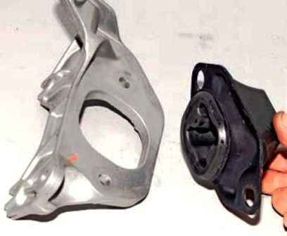
Disconnecting the support and the bracket
Install the left support of the power plant in reverse order.


