


The camshafts of the F4R and K4M engines are located in the upper part of the cylinder head.
One shaft opens the inlet valves and the other the exhaust valves.
Each shaft has eight cams.
A feature of the camshaft design is that the cams are press-fitted onto a tubular shaft.
The camshaft bearings (six supports for each shaft) are split – they are located in the cylinder head and in the cylinder head cover.
The camshafts are driven by a toothed belt from the crankshaft pulley.
On each camshaft, on the toothed pulley side, a thrust flange is provided which engages in a groove in the cylinder head, thereby preventing axial movement of the shaft.
The camshaft pulley is not fixed to the shaft by means of an interference fit, a key or a pin, but only by the friction forces generated on the end faces of the pulley and the shaft when the pulley retaining nut is tightened.
The camshaft nose is sealed by an oil seal fitted over the shaft journal and pressed into a seat formed by the surfaces of the cylinder head and the cylinder head cover.
To remove the camshafts, the following tools are required: 8, 10, 13, 16 spanners, 10, 16, 18, 17 sockets, Torx E14, Torx T8, Torx T14 keys, a bronze drift, an engine support, a TDC setting tool, a camshaft locking tool.
We prepare the vehicle to carry out the task.
We depressurise the fuel system (article – Replacing the additional fuel filter).
We disconnect the negative battery terminal.
We drain the coolant from the cooling system (article – Checking and replacing the engine coolant).
We remove the auxiliary drive belt (article – Checking and replacing the auxiliary drive belt).
We remove the timing belt, as described in the article – «Checking and replacing the timing belt».
We disconnect the downpipe from the exhaust manifold (article – Removing exhaust system components).
We remove the resonator (article – Removing and installing the engine resonator).
We remove the cylinder head cover (Removing the cylinder head cover).
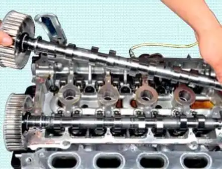
We remove the exhaust valve camshaft.
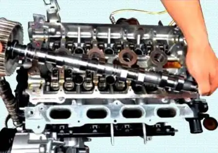
We remove the inlet valve camshaft.
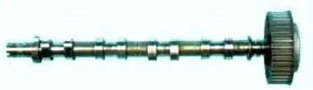
We inspect the camshafts for wear and defects.
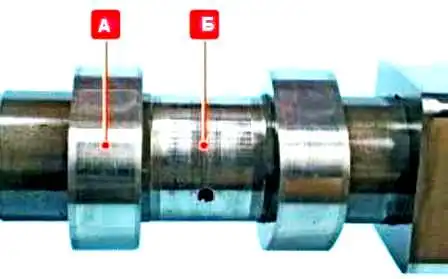
The surfaces of the bearing journals «Б» and the cams «А» must be well polished and free from damage.
Scoring, dents, scratches and aluminium pick-up from the bearing seats in the cylinder head are not permitted on the working surfaces of the journals.
If signs of seizure, overheating, deep scores or faceted wear are found on the working surfaces of the cams, as well as uniform wear exceeding 0.5 mm, the shaft must be replaced.
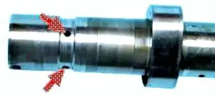
We thoroughly clean the oil supply channels of deposits.
The camshaft cams must not be ground to eliminate stepped wear, as changing the cam profile size would disrupt the valve timing.
We check the radial runout.
If the runout exceeds 0.02 mm, the shaft must be replaced, as straightening is not permitted.
We install the shafts in the reverse order.
When installing new shafts, it is recommended to install new valve rockers.
You can also look at the article — «Removing the camshafts and hydraulic valve lifters».


