Steering elements are removed for repair or replacement.
We discussed the removal of the steering wheel in the article - Removing and installing the steering wheel of a Renault Duster car
Removing the power steering pump and bleeding the system we examined in the article - Removing the power steering pump steering Renault Duster.
In this article, we will consider the removal of the remaining elements of the car's steering system
Removing the steering column
We remove the steering column for replacement as an assembly in case of failure of the column shaft bearings or intermediate shaft cardan joints.
Removing the steering column switches (article - Design and replacement of Renault Duster steering column switches) with coiled cable drum.
Remove the instrument cluster.
Disconnect the wire blocks of the ignition switch and the immobilizer coil from the wire harness blocks.
The steering column can be dismantled in two ways - with or without removing the instrument panel.
Let's consider both ways.
Removing the instrument panel (article - How to remove the Renault Duster instrument panel) .
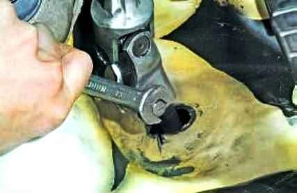
With a head of 13, we unscrew the nut of the special bolt securing the coupling of the lower cardan joint of the intermediate shaft to the steering gear shaft.
Remove the bolt.
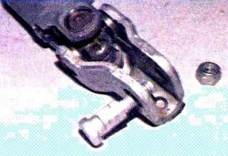
Special bolt and self-locking nut for intermediate shaft lower universal joint coupling
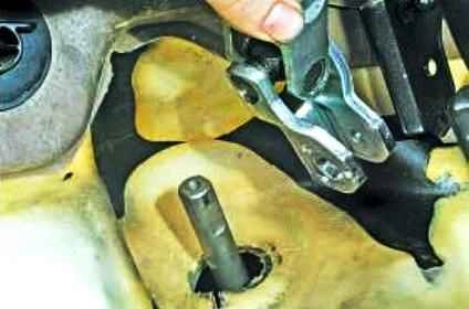
Remove the lower universal joint coupling from the pinion shaft
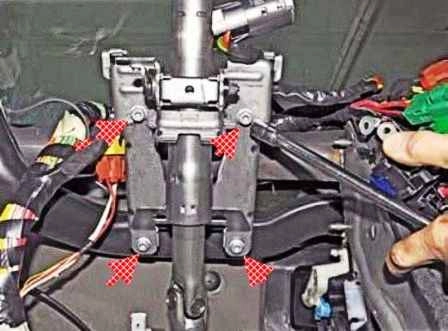
With a head of 13, we unscrew the four bolts securing the steering column to the bracket of the cross beam located under the instrument panel
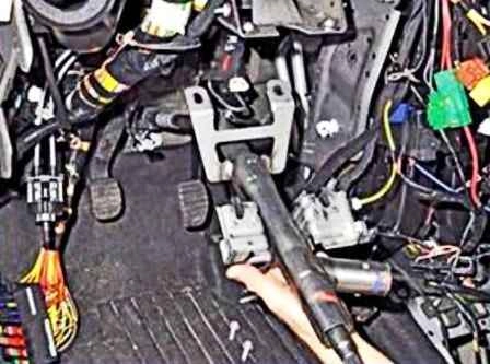
Remove the steering column.
To remove the steering column without removing the instrument panel:
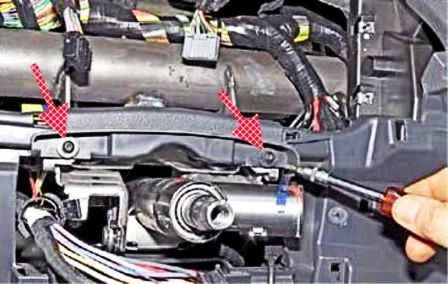
Using a Torx T-20 wrench, unscrew the two screws securing the instrument panel to the rear steering column mounting bracket
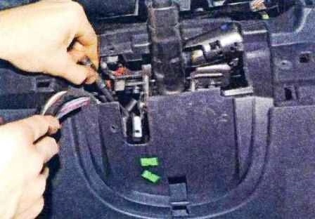
With a 13 head, we unscrew the two upper bolts securing the steering column to the cross beam bracket.
Unscrew the two lower steering column mounting bolts from under the instrument panel
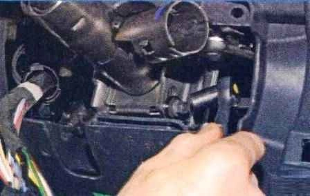
With a 10 head, we unscrew the nut of the steering wheel adjustment mechanism bolt
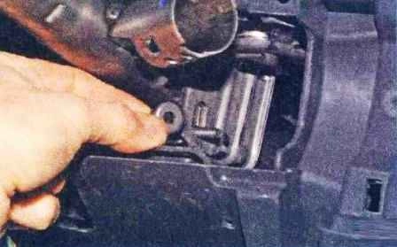
Remove the bearing
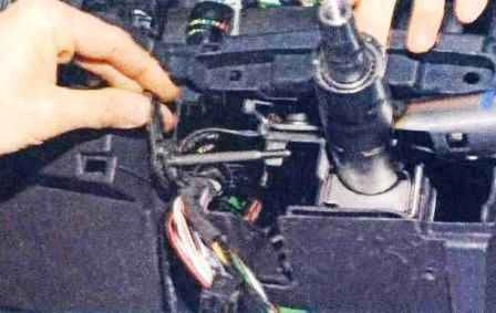
Remove the handle
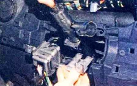
Remove the rear steering column mounting bracket.
Then, moving the upper part of the steering column so that it does not catch on the elements of the instrument panel and the cross beam, we push the column down through the hole in the instrument panel
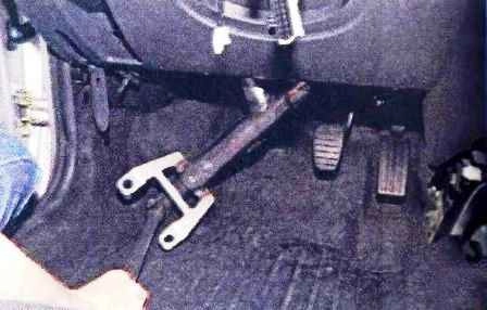
And remove the steering column.
Install the steering column in reverse order.
We mount the clutch of the lower cardan joint on the steering gear shaft so that the clutch mounting bolt is aligned with the flat of the gear shaft.
Tightening torques for steering fasteners:
- - steering wheel mounting screw - 44 Nm;
- - bolt for fastening the steering gear housing to the subframe - 125 Nm;
- - steering column bracket bolt - 21 Nm;
- - fastening the steering rod to the rack - 34 Nm;
- - tie rod end locknut - 50 Nm;
- - nut for fastening the ball pin of the thrust tip - 37 Nm;
- - hydraulic booster pump mounting bolt - 25 Nm;
- - nut of the coupling bolt of the universal joint of the steering shaft - 21 Nm.
Replacing the tie rod end
The tie rod end is replaced if its ball joint fails or the joint boot is damaged.
We work on a level ground
Remove the front wheel from the side of the tie rod end to be replaced and securely fix the car on the stand.
Turn the steering wheel all the way in the direction opposite to the tip to be removed.
The work is shown on the example of the left tie rod end, the right tie rod end is changed in the same way.
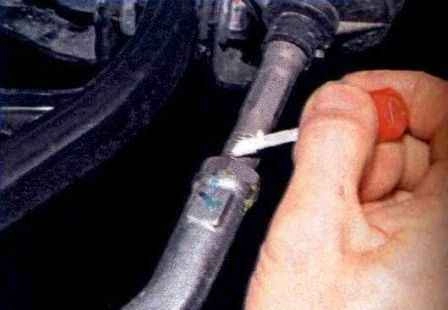
Marking the position of the tip relative to the tie rod
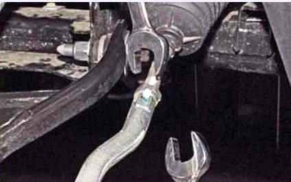
Using a 21 wrench, loosen the locknut, holding the tip with a 19 wrench by the flats.
Before unscrewing the nut that secures the tip hinge pin to the steering knuckle lever, we clean the Torx key hole at the end of the pin from dirt with a metal brush.
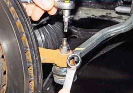
Using a 16 key, unscrew the nut that secures the tip hinge pin to the steering knuckle lever, if necessary, holding the finger from turning with a Torx T-30 key.
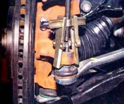
Using a puller, press the tip pin out of the steering knuckle eye
If there is no puller, we do not completely unscrew the finger nut.
Insert a mounting spatula between the tie rod end and the steering knuckle arm.
Pressing the tie rod end down with a mounting spatula, and striking with a hammer at the end of the steering knuckle lever, we press the finger out of the hole in the lever.
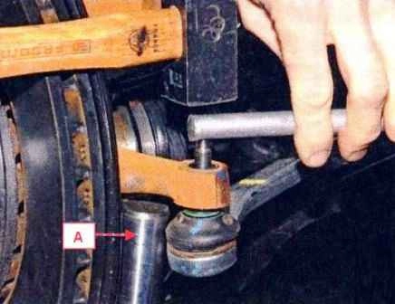
It is also possible to extrude a finger by striking with a hammer through a soft metal spacer on the end of the finger.
In this case, support the steering knuckle with an adjustable support "A".
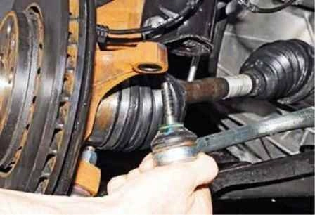
Remove the ball joint pin from the hole in the lever
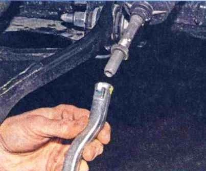
We unscrew the tip by hand, counting the number of turns it turns away, if necessary, keeping the steering rod from turning by the hexagon with a 13 wrench.
Install the tie rod end in reverse order.
We screw it onto the threaded end of the steering rod for the same number of turns (or up to the marked mark) on which it was screwed before removal.
Tighten the locknut of the tip and the nut of the ball joint pin to the prescribed torques.
After completing the installation of the tie rod end, it is necessary to check and, if necessary, adjust the toe-in of the wheels on a special stand - at a service station.
To adjust the toe-in of the wheel, it is necessary to loosen the tip locknut, remove the spring clamp and rotate the tie rod by the hexagon with a 13 wrench, holding the tip with a 19 wrench.
Tighten the locknut to the torque indicated above.
Replacing the steering cover
If the steering gear boot has lost its elasticity, cracked or torn, it must be replaced.
Remove the tie rod end as described above
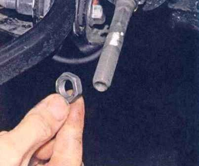
Unscrew the tie rod end locknut
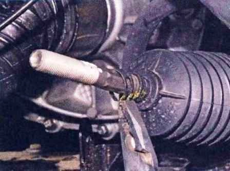
Pliers compress and remove the spring clamp of the cover
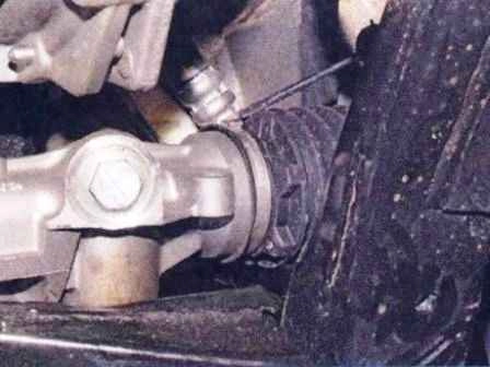
We bite with side cutters the clamp of the protective cover on the steering gear housing or unclench it with a screwdriver
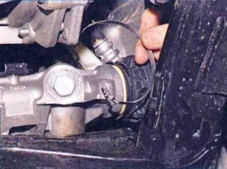
Remove the clamp
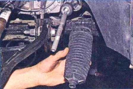
Remove the protective cover of the steering mechanism
Install the new case in reverse order.
Replacing the tie rod
We replace the tie rod when there is play in its ball joint.
We install the car on a viewing ditch or a lift.
Operations are shown on the left tie rod.
The right tie rod is removed in the same way.
Remove the tie rod end as described above.
Remove the protective cover.
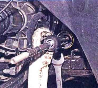
Using a #2 pipe wrench, we unscrew the tie rod joint housing from the rack, holding the rack by the first tooth with a 22 wrench.
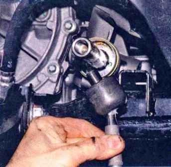
Remove the tie rod
Install the new tie rod in reverse order.
Before installation, apply a small amount of fixing sealant to the threaded part of the tie rod ball joint.
Check and, if necessary, adjust the toe angle.
Removing the steering gear
The steering gear is removed for repair or replacement. With the help of a pear, we pump out the liquid from the power steering reservoir.
Disconnect the ends of both steering rods from steering knuckles.
In the passenger compartment, disconnect the universal joint coupling of the intermediate shaft of the steering column from the steering gear shaft.
Before disconnecting the hydraulic lines from the crankcase of the steering mechanism, we substitute a wide container under the crankcase to collect fluid.
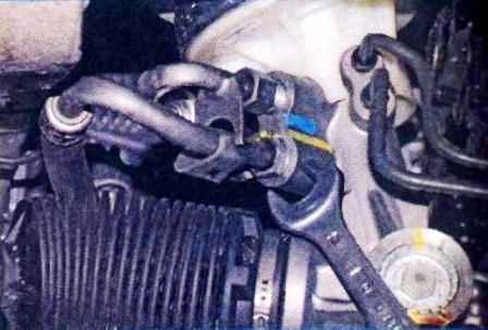
Use a 17 key to unscrew the fitting of the drain pipe
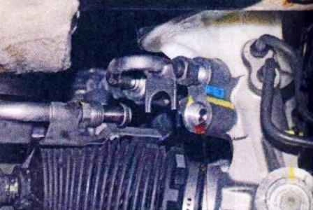
We remove the tip of the tube from the hole in the crankcase of the steering mechanism and insert plugs of a suitable diameter into the holes of the tube and crankcase.
We also disconnect the discharge line pipe.
The connection of the drain and discharge pipes is sealed with rubber rings.
We replace them if they have lost their elasticity, cracked or deformed.
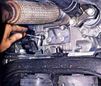
On the left side, with a 10 head, unscrew the bolt securing the bracket to the steering gear housing
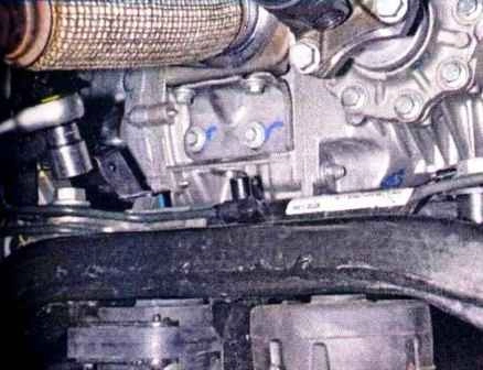
Using a 21 head, unscrew the bolt securing the steering gear housing and bracket to the front suspension subframe
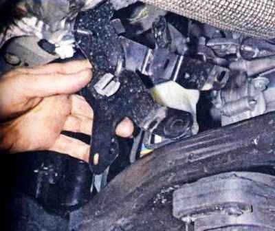
Having disconnected the wiring harnesses, remove the bracket.
We unscrew the bolt securing the steering gear housing to the front suspension subframe on the right side.
We substitute an adjustable stop under the back of the subframe.
Loosen the front bolts of the subframe to the body, approximately four turns.
We unscrew the rear bolts of the subframe to the body and remove the two subframe amplifiers
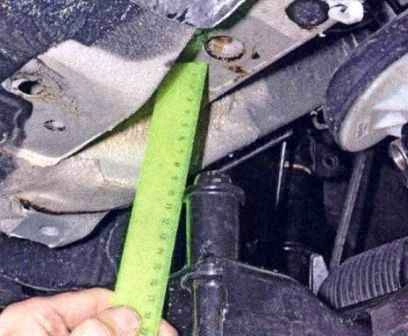
We lower the rear part of the subframe by 90-100 mm on an adjustable stop.
We remove the steering gear shaft from the hole in the bulkhead.
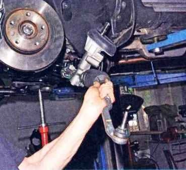
We take out the steering mechanism through the arch of the left wheel.
Install the steering gear in reverse order.
Before installation, we check that the rail is set to the middle position.
We tighten the bolts and nuts with the moments indicated in this article.


