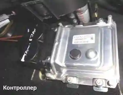
The controller is the central unit of the engine management system.
It receives information from sensors and controls the actuators, ensuring optimal engine operation at a given level of vehicle performance.

The controller is located in the area of the passenger's feet and is attached to the bulkhead.
Marking of the controller ME17.9.71 2123-1411020-50 from BOSCH
The controller controls actuators such as fuel injectors, motorized throttle, ignition coil, oxygen sensor heater, canister purge valve, and various relays.
The controller controls the on and off of the main relay (ignition relay), through which the supply voltage from the battery is supplied to the elements of the system (except for the electric fuel pump, electric fan, control unit and APS status indicator).
The controller turns on the main relay when the ignition is turned on.
When the ignition is turned off, the controller delays turning off the main relay for the time necessary to prepare for the next turn on (completion of calculations, setting the throttle to the position before starting the engine).
When the ignition is turned on, the controller, in addition to performing the functions mentioned above, exchanges information with the APS if the immobilization function is enabled.
If the exchange determines that access to the vehicle is allowed, then the controller continues to perform engine control functions.
Otherwise, the engine will be blocked.
The controller also performs a system diagnostic function.
It determines the presence of malfunctions of system elements, turns on the alarm and stores codes in its memory that indicate the nature of the malfunction and help the mechanic to carry out repairs.
The controller is a complex electronic device and should only be repaired at the factory.
During the operation and maintenance of the vehicle, disassembly of the controller is prohibited.
Unauthorized modification of the controller software may result in poor engine performance and even damage.
In this case, the warranty obligations of the vehicle manufacturer for the maintenance and repair of the engine and control system are lost.
The controller supplies various devices with 5 or 12 V power supply.
In some cases, it is supplied through the resistors of the controller, which have such a high nominal resistance that when the control light is connected to the circuit, it does not light up.
In most cases, a conventional voltmeter with low internal resistance will not give accurate readings.
To control the voltage of the controller output signals, you need a digital voltmeter with an internal resistance of at least 10 MΩ.
Controller memory
The controller has three types of memory: Programmable Read Only Memory (ROM), Random Access Memory (RAM), and Electrically Reprogrammable Memory (EPROM).
Read Only Memory (ROM)
The ROM stores the control program, which contains the sequence of operating commands and calibration information.
Calibration information is injection, ignition, idle control data, etc., which in turn depend on vehicle weight, engine type and power, transmission ratios, and other factors.
This memory is non-volatile, ie. its contents are saved when the power is turned off.
Random Access Memory (RAM)
Random access memory is used by the microprocessor for temporary storage of measured parameters, calculation results, fault codes.
The microprocessor can write or read data into RAM as needed.
This memory is volatile.
When power is interrupted (disconnecting the battery or disconnecting the harness from the controller), the diagnostic trouble codes and calculated data contained in the RAM are erased.
Electrically Reprogrammable Memory (EPROM)
EEPROM is used to store controller, engine and vehicle identifiers, as well as vehicle anti-theft system (ATS) passcodes.
The password codes received by the controller from the APS control unit are compared with those stored in the EEPROM and changed by the microprocessor according to a certain law.
EPROM is a non-volatile memory, its contents are saved when the power is turned off.
Replacement controller
To prevent damage to the controller, when disconnecting the wire from the negative terminal of the battery or the wiring harness from the controller, the ignition must be turned off.
Remove controller
Turn off the ignition.

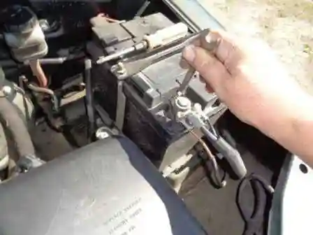
Disconnect the negative battery terminal

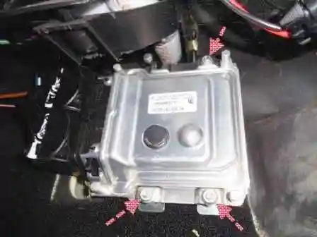
Unscrew the nuts securing the controller and remove the controller by disconnecting the wiring harness blocks from it.
Only remove the pads from the controller when the controller is removed.
In the event of a controller malfunction, a "clean" controller must be used for replacement.
Installing the controller
Connect the wiring harness pads to the controller.
Install the controller on the car.
Connect the wire to the negative terminal of the battery.
Checking if the controller is working
After replacing the controller or resetting the controller using the scan tool (mode "5 - Advanced tests; 1 - ECU reset with initialization"), the throttle zero adaptation procedure and the misfire diagnostic function adaptation procedure must be performed.
Throttle Zero Adaptation Procedure:
- with the car at a standstill, turn on the ignition, wait 30 seconds, turn off the ignition, wait for the main relay to turn off.
Adaptation will be aborted if:
- - the engine scrolls;
- - car is moving;
- - accelerator pedal pressed;
- - engine temperature below 5° C or above 100° C;
- - ambient temperature is below 5°C.
Procedure for adapting the misfire diagnostic function:
- - warm up the engine to operating temperature (monitored parameter TMOT_W = 60...90° С);
- - accelerate the car in 2nd gear until the increased crankshaft speed is reached (NMOT_W = 4000 min-1) and apply engine braking (NMOT_W = 1000 min-1 );
- - perform engine braking six times in one trip.
Perform diagnostics.


