A worn/poorly installed belt and tensioner or a misaligned pulley can cause the belt to come off
This may cause the coolant pump and/or fan to slow down, causing the engine to overheat.
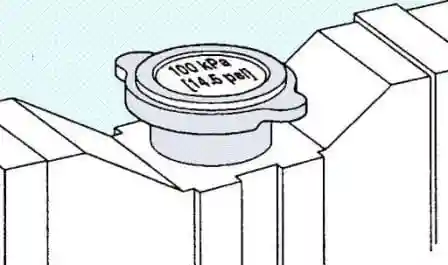
When diagnosing engine cooling problems, the radiator/expansion tank cap is usually the one that gets the least attention.
The cooling system uses a sealed radiator cap to prevent fluid from boiling over.
Incorrect selection of a cover or its malfunction can also lead to leakage of coolant and overheating of the engine.
See original equipment documentation for heatsink cap specifications.
The air passing through the radiator fins due to the rarefaction created by the fan removes heat from the coolant, which is pumped through the radiator by a water pump.
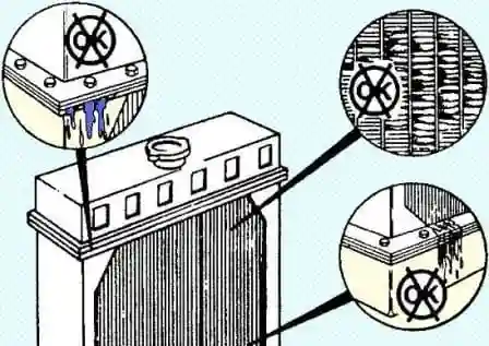
Foreign objects (paper scraps, dry grass, fabric fibers, dust, etc.) may get stuck between the fins, preventing air flow. This will reduce the efficiency of the radiator.
The radiator should be checked periodically for bent or broken fins and coolant leaks.
If the fan is belt-driven, slippage of the belt can cause the fan to slow down and reduce the cooling efficiency of the motor.
The problem may also be related to a malfunction of the automatic belt tensioner.
Check the bearings in the fan hub and other pulleys to make sure they are not causing excessive vibration or belt slippage.
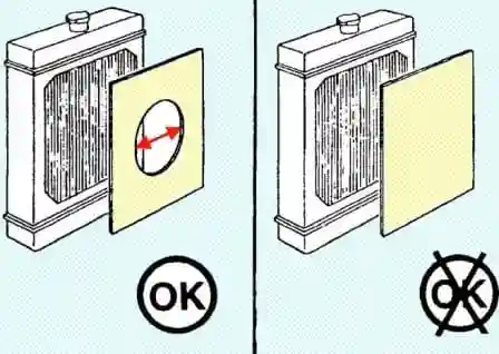
Insulation covers can be used to reduce engine warm-up time and help keep the engine warm in cold climates.
Insulation covers should cover only part of the radiator from the front, leaving room for air to pass through.
If you do not leave part of the front side of the radiator open to airflow or do not remove the insulation covers when the ambient temperature rises, this can lead to overheating of the engine.
If the radiator is combined with an aftercooler, installing a boot without a hole will result in poor charge air cooling.
Do not install homemade cardboard cases, because. the products of destruction of such a heater will lead to severe contamination of the radiator and the intercooler of the charge air.
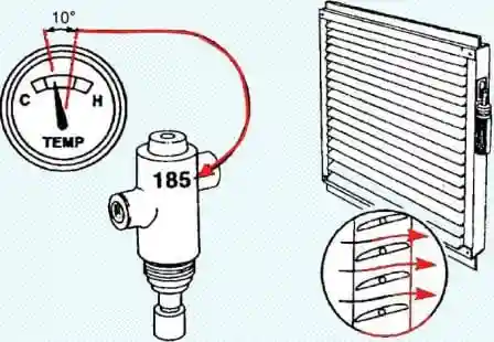
If the vehicle is equipped with thermostatic shutters, check the coolant temperature at which the shutters open and close.
Compare the result with the value indicated on the blind control.
Cummins recommends opening the shutters when the coolant temperature reaches 85°C.
If the engine is equipped with a temperature controlled cooling fan clutch, check the coolant temperature at which the fan clutch engages.
Cummins recommends turning on the fan when the coolant temperature reaches 96°C.
If the engine is equipped with a viscous fan clutch, check the temperature of the coolant at which the fan turns on.
Note: some models of viscous fan couplings may be electronically controlled.
If the air temperature reaches a predetermined level, which is determined by the temperature setting of the sensor used, the temperature sensor moves the actuator, which allows the viscous fluid to turn on the fan drive and increase its speed.
Cummins recommends turning on the fan when the coolant temperature reaches 96˚C.
Removing and installing the coolant pump
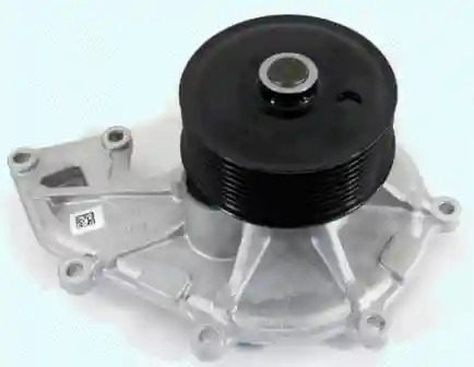
Attention: If there is a persistent coolant leak, replace the coolant pump.
Drain the coolant.
Remove the accessory drive belt.
Remove the 8 mounting bolts and remove the coolant pump. Tightening torque 8 Nm
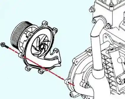
Clean the surfaces of the coolant pump.
Install the coolant pump in the reverse order of removal.
Check
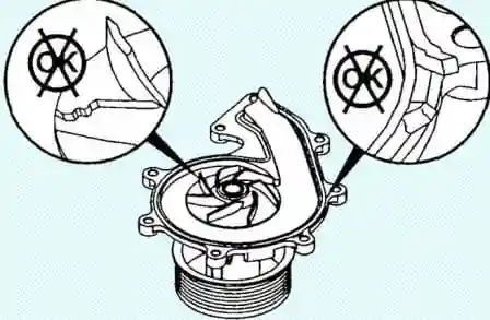
Check that the coolant pump impeller is not nicked or damaged. If there is damage, the impeller must be replaced.
Inspect the water pump seal for damage.
If there is damage, the seal must be replaced.
Thermostat
Note: The thermostat housing is part of the intake manifold, if the thermostat housing is damaged, the intake manifold must be replaced.
Check before removal
After closing the thermostat for 1 minute with the engine running, do the following:
- to control the temperature of the coolant, connect the diagnostic tool.
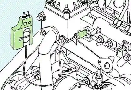
Disconnect the radiator hose from the coolant outlet.
Install the hose on the outlet pipe of the cooling system, tighten the clamp and lower the free end of the hose into a measuring container.
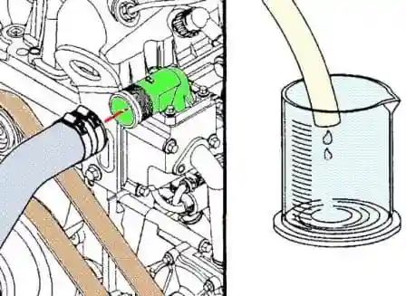
Start the engine and warm it up at rated speed for one minute while watching the thermostat open.
If the thermostat opens during this test, repeat the test. Permissible coolant temperature 38˚ С
Stop the engine and measure the amount of coolant in a graduated container.
If the volume of liquid collected is greater than the allowable one, the thermostat must be replaced.
Permissible volume 100 cm3
Removing and installing thermostat
Disconnect the cable from the negative battery terminal.
Drain the coolant.
Remove the mounting bolt, remove the bypass pipe of the cooling system and the O-ring.
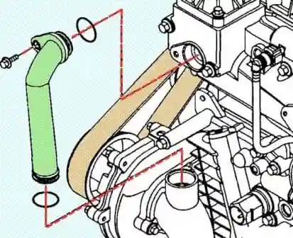
Disconnect the upper radiator hose from the cooling system outlet.
Remove the bolts securing the cooling system outlet pipe.
Remove the cooling system outlet pipe.
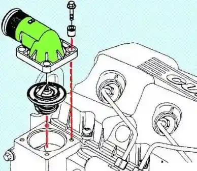
Remove thermostat
Install the thermostat
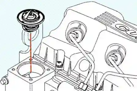
Install the cooling system outlet and tighten the mounting bolts. Tightening torque 7 Nm
Connect the upper radiator hose to the cooling system outlet.
Install the cooling system bypass.
- a) Install a new O-ring.
- b) Install the cooling system bypass pipe and tighten the mounting bolt. Tightening torque 24 Nm
Refill coolant.
Connect the cable to the negative battery terminal.
Start the engine and check for leaks.
Check a
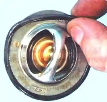
Note: as a rule, numbers indicating the temperature at which the valve starts to open are printed on the thermostat housing.
Clean the contact surfaces using an abrasive sponge.
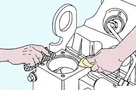
Check the thermostat seal for damage. If there is damage, the thermostat must be replaced.
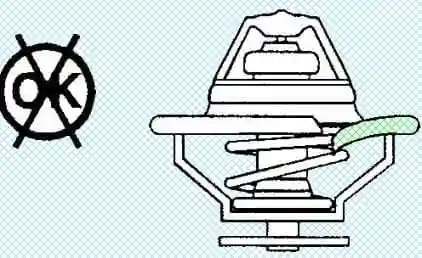
Check the thermostat opening temperature.
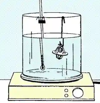
a) Dip the thermostat and thermometer in a container of water and heat slowly.
Note: The thermostat and thermometer must not touch the sides of the container.
b) Check the opening temperature of the thermostat valve.
The temperature of the beginning of opening is 79 - 8˚ C
Full opening temperature 94˚ C
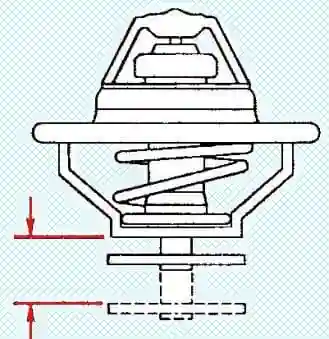
Check the cooling system bypass
- a) Clean the nozzle with soapy water.
- b) Dry with compressed air.
c) Clean the O-ring grooves.
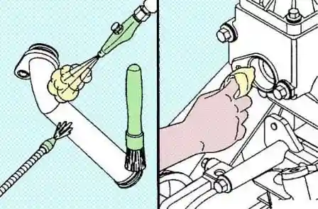
d) Check that the O-ring groove is not damaged.
If there is damage, replace the overflow pipe.
Removing and installing the coolant heater
Disconnect the cable from the negative battery terminal.
Drain the coolant.
Disconnect the wiring from the coolant heater.
Disconnect the coolant heater. Tightening torque 55 Nm
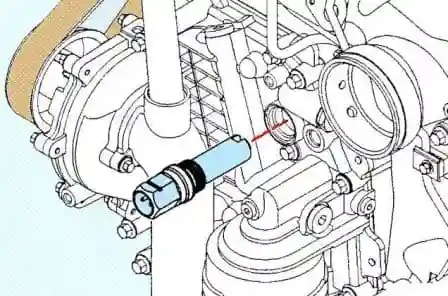
Apply a coat of sealant to the heater threads.
Sealant 3375066 or equivalent
Install the coolant heater in the reverse order of removal.
Check
Clean the hole for the coolant heater.
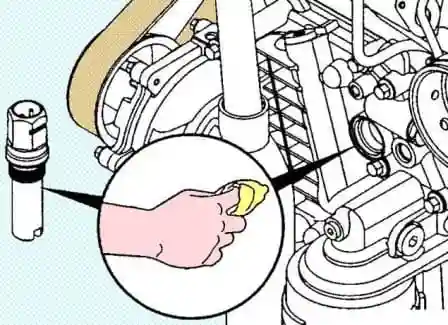
Check for thread damage.
Clean the heater with a rag.
Check for deposits and cracks on the heating element and O-ring.
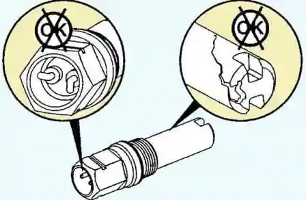
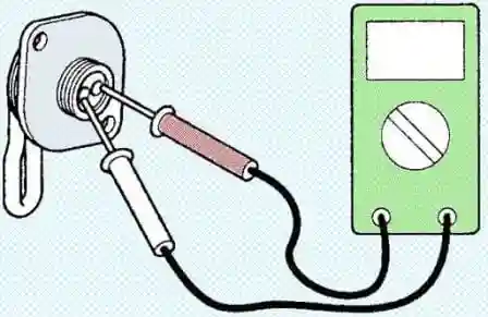
Check the coolant heater resistances.
It must be within acceptable limits.
Coolant heater resistance:
- - minimum value 18.2 Ohm;
- - maximum value 21.1 Ohm.
Removing and installing the cooling fan
Disconnect the cable from the negative battery terminal.
Remove the accessory drive belt (Article - Replacing the Cummins ISF3.8 Attachment Drive Belt)
Remove the fan shroud.
Remove the 4 fan mounting bolts, remove the fan and spacer.
Please do not hold the fan by its blades. Torque:
- - M6 - 10 Nm;
- - M10 - 43 Nm;
- - M12 - 77 Nm.
Remove the fan pulley.
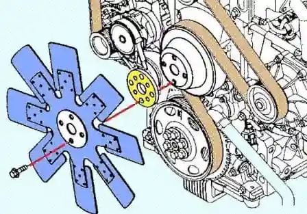
Remove the four fan hub mounting bolts and remove the fan hub. Tightening torque 33 Nm
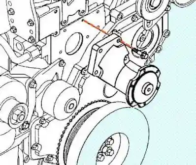
Install the cooling fan in the reverse order of removal.
Check
Clean the pulley, spacer and fan hub with solvent and dry with compressed air.
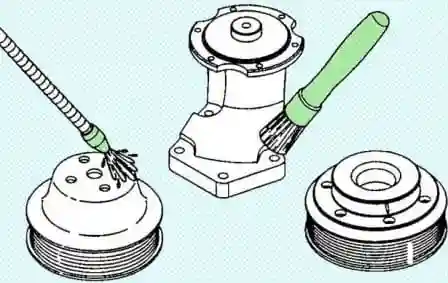
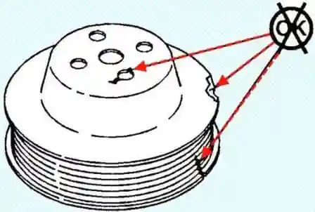
Check for damage or cracks on the fan pulley.
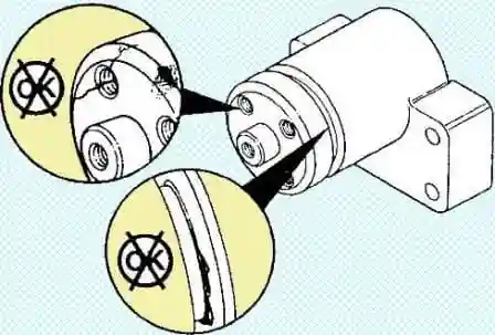
Inspect the fan hub, bevel of the hub for damage, and check the fan hub for signs of seal failure.
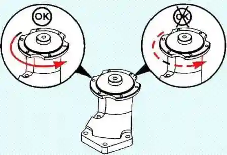
Rotate the fan hub and make sure it rotates smoothly and quietly.
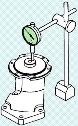
Check the fan hub bearing.
- a) Check the bearing for wear.
- b) Check the radial and axial play of the bearing. Replace the fan hub if the end play exceeds the maximum value.
Maximum axial play of the fan hub 0.15 mm
Check for damage, loose bolts, bent or loose blades on the cooling fan.
Replace the fan if necessary. When replacing the fan, use the part with the same part number.
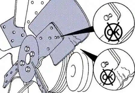
Note: Do not straighten a bent fan blade, but replace the cooling fan.
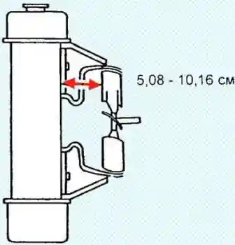
Check the fan shroud for damage.
Check the gap between the fan shroud and the fan, it should be within tolerance.
Gap limits 5.08 - 10.16 cm
Radiator
Cleanup
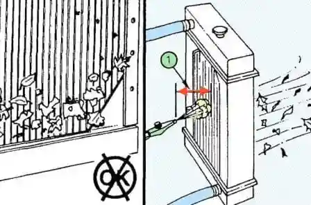
Blow the radiator with compressed air to remove dirt from its core.
Air pressure 552 kPa
Note Keep the hose nozzle at least 15 cm away from the radiator core. so as not to damage the radiator.
Check
Inspect all hoses for cracks, cuts, or kinks. Replace hoses if necessary.
Check for damage or leaks to the radiator and radiator gasket.
Remove the radiator cap.
Attention: on a hot engine, this operation must be carried out with care, as water and steam are under pressure.
Check the radiator cap using a radiator tester.
Note: if there are traces of liquid and / or foreign deposits on the lid, rinse and blow the lid.
While moving the tester piston, evenly and slowly (1 stroke of the tester piston in 1 second) pressurize the steam valve of the radiator cap and check that the valve opens breaks under air pressure.
The radiator cap must provide tightness within 14 kPa of the value indicated on the cap.
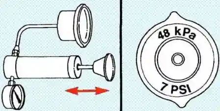
If the valve opening pressure is less than the minimum, replace the radiator cap.
Check the cooling system for leaks.
а) Fill the system with coolant and connect the tester with a hose to the radiator neck, as shown in the figure.
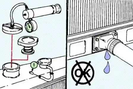
- b) Warm up the engine.
- c) Using a tester, pressurize the system to 138 kPa and check that the pressure does not decrease.
If there is a drop in pressure, check the radiator and pump hoses for leaks.
Install the radiator cap.


