
In the article, we will consider checking the elements of the battery charging system.
Inspection Precautions
Make sure the battery wires are connected to the correct terminals.
When accelerating the battery charge, disconnect the wires from its terminals.
When measuring, do not use a high-voltage tester with a large input resistance.
Do not disconnect the wires from the battery terminals while the engine is running.
Disconnect the negative battery terminal first and reconnect it last.
There are several types of generators used with this engine:
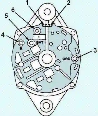
- Delco-Remy three-phase generator;
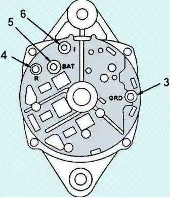
- Delco-Remy single-phase generator;
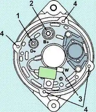
- Bosch generator.
Schemes of starting and charging systems for cars with an ISF3.8 engine are presented in the article - Checking the elements of the Cummins ISF3.8 starting system
Checks on the car
Inspect the battery. If you find serious damage or electrolyte leakage, replace the battery.
Disconnect and check for damage or corrosion on battery terminals and cables. Replace them if necessary.
If corrosion is found on the terminals, clean to a shine with a brush.

Inspect the accessory drive belt for damage and excessive wear and make sure it is properly seated in the pulley grooves.
Replace the belt if necessary.
Check the fastening of the alternator pulley on the shaft. If it is loose, remove the pulley and check for damage.
If the generator does not rotate or rotates with difficulty, it must be replaced.
Check the low battery warning light circuit.
Warm the engine up to operating temperature and stop it.
Turn off all accessories.
Turn the ignition key to the "ON" position. The battery discharge indicator lamp should light up.
Start the engine. The lamp should go out. If the conditions are not met, continue checking.

If the lamp comes on when the ignition key is in the OFF position and the engine is not running, disconnect the lamp connector from the ignition switch.
If the lamp stays on, there is a short to positive in the wiring.
If the lamp goes out, there is a short circuit in the ignition switch.

If the lamp does not come on when the ignition key is in the "ON" position and the engine is not running, there is an open in the circuit.
Check for a blown fuse, a blown bulb from a faulty socket, or an open circuit between the alternator and the ignition switch.

If the lamp is on, the ignition key is in the ON position, and the engine is running, disconnect the ignition switch lamp lead.
If the lamp stays on, there is a short to ground in the wiring.
If the lamp goes out, check the alternator

Check the electrolyte level and density in each section of the battery.
Check the generator for open circuits with a tester.
Note if the tester shows no voltage, there is an open in the circuit.
Connect a tester to the following pins and repair the open, if any:
Between the alternator battery positive terminal and ground.
Between the flat terminal "L" of the generator and the "ground".
Between the flat terminal "W" of the generator and the "ground".

Check the voltage and current supplied by the alternator to the batteries without load (at idle).
Disconnect all battery terminals that go to other batteries.
Connect a digital tester and, at 2000 rpm, measure the voltage.

While keeping the engine running at 2000 rpm, adjust the battery tester so that the load on the alternator matches the maximum amperage rating.
Measure the generator output current.
If the output current differs from the nominal by more than 10%, the generator must be repaired or replaced.
Note: The maximum generator output current rating is stamped on the generator.

Stop the engine and disconnect the test equipment. Connect the terminals to the battery.
Removing and installing the generator
Disconnect the cable from the negative battery terminal.
Remove the accessory drive belt.
Tag all generator wires and disconnect them.
Remove the generator.
Lever mounted generator:
Remove the alternator bracket bolt. Tightening torque 40 Nm
Remove the mounting bolt and remove the generator support bracket and the generator itself. Tightening torque 24 Nm

Generator on support platform:
Remove the mounting bolts and remove the generator.
Tightening torque:
- - M10 - 36 Nm;
- - M12 - 64 Nm

Articulated Generator:
Remove the alternator bracket bolt. Tightening torque 24 Nm

Remove the alternator mounting bolt and remove the alternator. Tightening torque 40 Nm

Remove the alternator bracket mounting bolts and remove the alternator bracket. Tightening torque 45 Nm

Installation is performed in the reverse order of removal.

")
")
")
")
")
")
")
")