To check the elements of the engine starting system, you will need a digital tester and connecting wires.
Checking the operation of the ignition switch
Disconnect the wire connecting the ignition switch to the starter intermediate relay (labeled “S” or “Start”) from the ignition switch terminal.
Connect the positive lead of the digital tester to the ignition switch and the negative lead to chassis or engine ground.
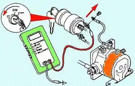
Put the tester into DC voltage measurement mode by turning the ignition switch to the “OFF” position. There should be no voltage at the ignition switch.
Otherwise, replace the ignition switch.
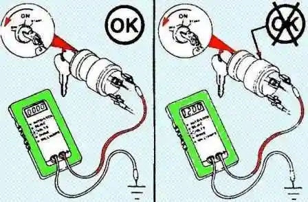
Turn the key in the ignition switch to the “Start” position. In this case, the tester must show the rated voltage.
If there is no voltage, continue testing.
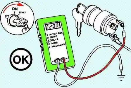
Turn the ignition key to the “OFF” position.
Check the voltage in the ignition switch supply circuit by connecting the positive lead of the tester to the ignition switch terminal, which has a wire going to the ‘B’ terminal of the starter relay.
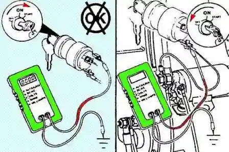
Turn the key in the ignition switch to the “Start” position.
If the tester shows the nominal voltage at the input terminal of the ignition switch, then the ignition switch must be replaced.
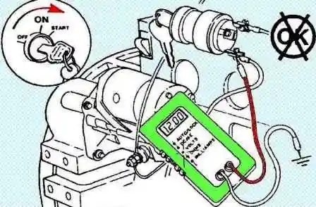
If the tester does not indicate the presence of voltage, then the ignition switch is not the cause of the malfunction.
The wiring, starter relay and battery need to be checked.
Checking the intermediate starter relay
Disconnect the terminal connecting the intermediate relay to the starter solenoid relay.
Connect the leads of the digital tester to the ignition switch terminals.
Put the digital tester into resistance measurement mode.
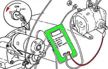
Connect the tester leads to the two intermediate relay terminals.
If the key in the ignition is in the “OFF” position, the tester should show a resistance of more than 100 kOhm.
If the resistance is lower, replace the intermediate relay.
Turn the key in the ignition switch to the “Start” position.
The tester must show resistance less than 10 ohms.
If there is more resistance, continue testing.
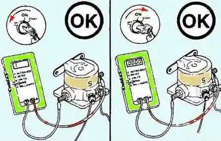
Turn the ignition key to the “OFF” position.
Put the digital tester into voltage measurement mode.
Connect one lead of the tester to the "S" terminal of the intermediate relay, and the other to the "ground".
Turn the ignition key to the “START” position.
If the tester does not indicate the presence of voltage, the intermediate starter enable relay is not the cause of the malfunction.
If voltage is present, the intermediate relay must be replaced.
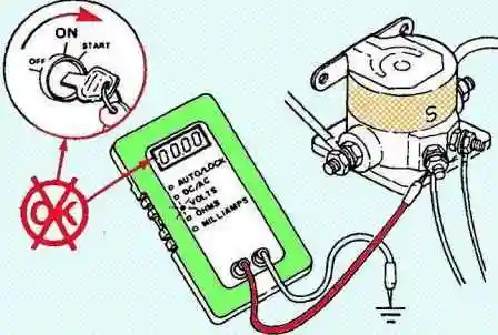
Turn the ignition key to the “OFF” position.
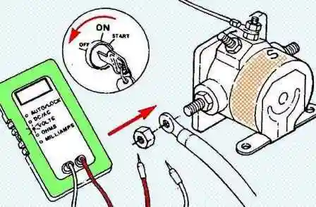
Disconnect tester leads and connect the terminal connecting the intermediate relay to the starter traction relay.
Checking the starter traction relay
Connect the positive lead of the tester to the positive terminal of the starter traction relay, and the negative lead of the tester to chassis or engine ground.
The tester should indicate the presence of voltage (12 V or 24 V DC, depending on the system) when the ignition switch is in the “OFF” position, while the starter should work.
If the tester does not show voltage, check for a broken wire connecting the starter relay to the battery.
Check for loose or corroded terminal connections.
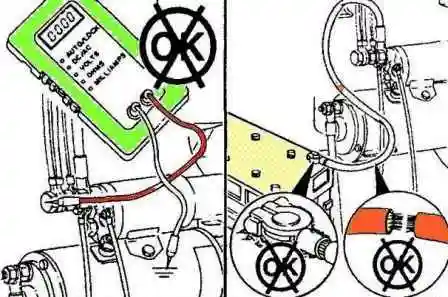
If the tester shows voltage, but the starter does not operate, check for broken wire connecting the starter relay to the ignition switch, fuses, engine shutdown systems and check for corrosion on the terminals.
If the wire connecting the starter relay to the ignition switch is not damaged, and the starter does not work, then do the following:
- a) Disconnect the wire connecting the traction relay to the starter from the relay terminal.
- b) Connect the tester's positive lead to the “S” terminal of the starter or intermediate starter relay, and the negative lead to chassis or engine ground.
- c) Turn the ignition key to the “START” position.
- If the tester shows the presence of voltage, and the starter does not work, then the starter relay must be replaced.
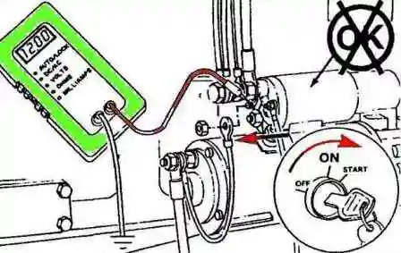
- If the tester does not indicate the presence of voltage, then check the wire connecting the “S” terminal of the starter relay or the ignition switch terminal to the intermediate starter relay for breaks and loose or corroded connections.
If there is no damage, replace the starter.
Checking the operation of the starter
Clean the starter connectors and check for damage.
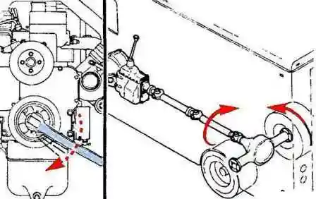
If you can hear the traction relay working, but the engine is not running, turn the ignition key to the “OFF” position and try turning the crankshaft using special tool #3824591.
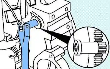
If the crankshaft turns, try starting the engine.
If the starter turns the crankshaft, check for damage to the starter gear and flywheel ring gear. Replace if damaged.
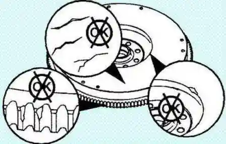
If the crankshaft does not rotate, or when cranking requires increased force, then check for internal damage or failure of the drive and auxiliary units.
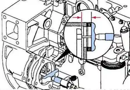
Measure the distance from the starter support flange to the front surface of the flywheel ring gear.
Distance:
- - maximum 52.32 mm;
- - minimum 49.28 mm.
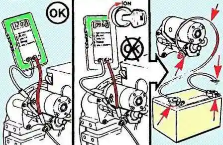
Check the voltage at the starter terminals while it is running.
If it drops more than 2.4V at 12V and more than 4.8V at 24V, make sure all connectors are clean and secure.
If the wiring is good and the voltage drop is abnormal, replace the starter.
Removing and installing the starter
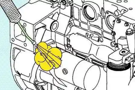
Disconnect the cable from the negative battery terminal.
Tag all starter wires and disconnect them.
Steam clean the surfaces around the starter motor and dry with compressed air.
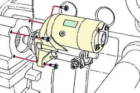
Remove the three bolts and remove the starter
Starter installation
Install the starter and tighten the three bolts. Tightening torque 43 Nm
Connect the wiring to the starter. Torque:
- - M5 - 4Nm;
- - M10 - 21 Nm.
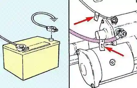
Connect the cable to the negative battery terminal.
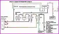
In Figure 20, a diagram of the launch and charging system for GAZ Valdai ISF3.8 Euro-4
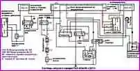
In Figure 21, a diagram of the PAZ 4234-05 starting and charging system from 2011
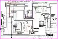
In Figure 22, a diagram of the PAZ 4234-05 starting and charging system from 2013
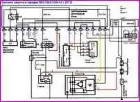
In Figure 23, a diagram of the PAZ 3204/3204-12 launch and charging system from 2013


