After removing the engine from the car, install it on the stand.
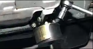
With a ring wrench or a 17 head, unscrew the nut securing the power unit support to the bracket.
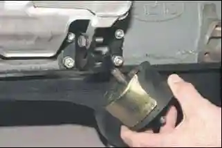
Remove the support
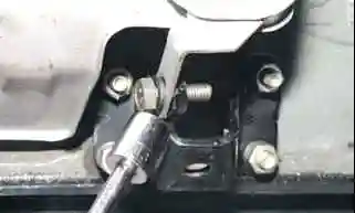
Using a 13 key, we unscrew the bolt securing the starter shield to the bracket
We unscrew the four nuts securing the bracket to the cylinder block.
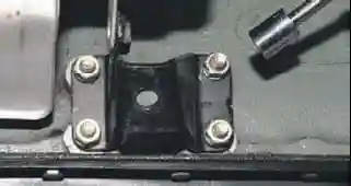
Remove the bracket from the cylinder block studs.
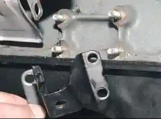
We unscrew the four nuts and remove the bracket for the left engine mount.
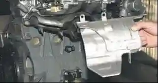
Using a 13 wrench, unscrew the two nuts securing the starter shield to the exhaust manifold, and remove the shield
Remove the ignition module; knock sensor; generator;
- - generator bracket; oil filter bracket; crankcase ventilation oil separator;
- - oil pump; coolant pump; flywheel and clutch housing cover;
- - cylinder head assembly with receiver, intake pipe and exhaust manifold;
- - timing chain, chain tensioner shoe, crankshaft sprocket; oil pump drive shaft.
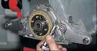
With a head of 10, we unscrew the six bolts securing the crankshaft rear oil seal holder to the cylinder block
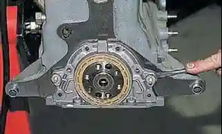
We pry off the tides of the holder with a screwdriver and remove it complete with the stuffing box.
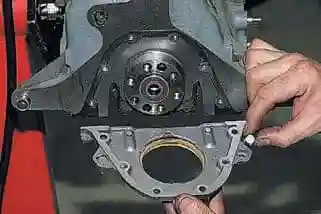
Remove two square head bolts from the stuffing box cover.
Remove the gasket.
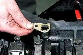
Using a 10 key, unscrew the bolt securing the bracket for the oil separator drain tube and remove the bracket
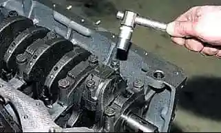
With a 14 head, unscrew the two nuts securing the connecting rod cap
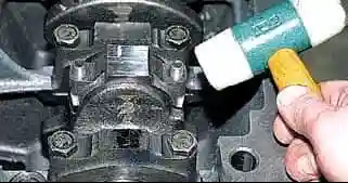
Knocking with a plastic hammer on the surfaces of the connecting rod cap
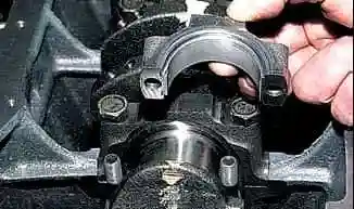
Remove the connecting rod cover
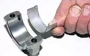
Remove the lower connecting rod
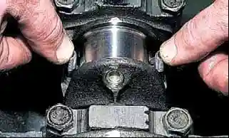
Leaning on the ends of the rods of the connecting rod bolts, we shift the lower head of the connecting rod from the crankshaft journal
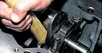
With the wooden handle of the hammer, we rest against the lower head of the connecting rod and push the piston into the cylinder
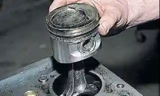
Remove the piston with the connecting rod from the cylinder. We also remove pistons from other cylinders.
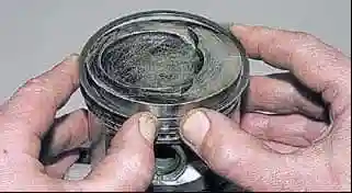
Unlock the upper compression ring
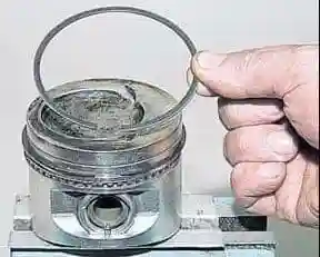
Remove the top compression ring.
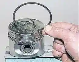
Also remove the lower compression ring
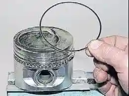
We take out two oil scraper discs.
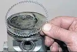
Remove the oil scraper ring expander
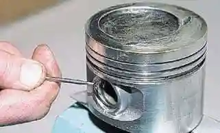
To remove the piston from the connecting rod, pry off the piston pin circlip with a screwdriver
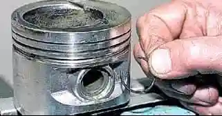
Remove the ring from the piston boss groove. In the same way, take out the second retaining ring
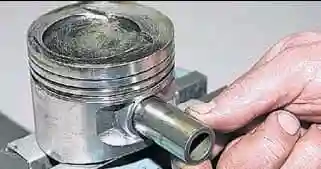
Sliding the piston pin, remove it from the holes in the piston and in the connecting rod head
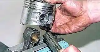
Remove the piston from the connecting rod
If the parts will be reused, then you need to mark them.
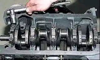
Using a 17 head, we unscrew the two bolts securing the crankshaft main bearing cap.
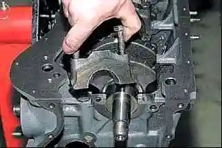
Remove the main bearing cap
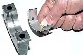
Remove the main bearing shells from the cover.
Also remove the remaining main bearing caps
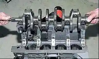
Remove the crankshaft from the block.
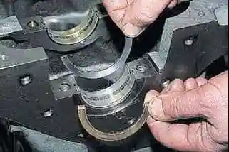
We take out the semi-rings from the grooves of the rear support of the cylinder block.
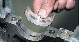
Remove the upper crankshaft main bearing shells from the cylinder block supports.
Engine parts troubleshooting
After dismantling the engine, you need to thoroughly wash all the parts with gasoline and remove carbon deposits.
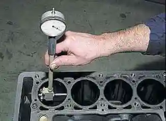
We measure the diameter of the cylinders with a bore gauge in four belts (at a distance of 8, 15, 50, 90 mm from the upper plane of the block) and in two directions (parallel and perpendicular to the axis of the crankshaft).
If wear exceeds 0.15 mm, it is necessary to bore the block to a repair size of 0.4 or 0.8 mm.
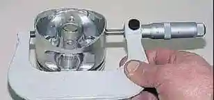
To determine the wear of the piston skirt, measure the diameter with a micrometer in a plane perpendicular to the axis of the piston pin, at a distance of 55 mm from the piston crown.
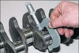
We measure the diameters of the connecting rod journals of the crankshaft with a micrometer
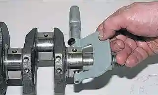
Measure the diameters of the main journals of the crankshaft
The crankshaft journals are ground to the nearest repair size if their ovality is greater than 0.03 mm, and also if there are scratches and marks on the journals.
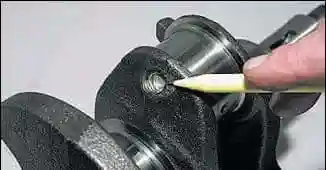
After grinding, remove the plugs from the oil channels and remove the remaining abrasive and deposits.
Installing new stubs
Engine assembly
Assemble the engine in reverse order. We install new crankshaft bearing shells in size.
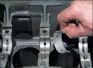
In the first, second, fourth and fifth supports of the block, we install the upper liners of the main bearings with grooves, and in the third support, the liners without grooves on the inner surface.
We apply a thin layer of engine oil to the working surfaces of the main bearing shells and lay the shaft.
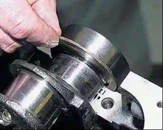
We insert thrust half rings lubricated with engine oil into the grooves of the fifth support.
On the front side of the fifth support, we install a steel-aluminum semi-ring, and on the back side, a ceramic-metal (yellow) one.
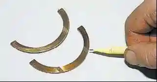
The working surfaces of the semi-rings with an anti-friction coating (grooves are made on them) must face the thrust surfaces of the crankshaft.
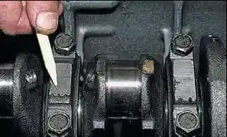
We install the main bearing caps with liners in accordance with the marks printed on the outer surface of the caps (the count is kept from the side of the camshaft drive).
The earbud locks must be on the same side.
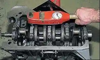
We tighten the bolts of the main bearing caps with a torque of 68.31-84.38 Nm (6.97-8.61 kgf.m).
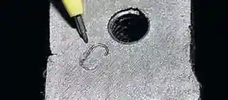
Pistons for cylinders are selected by class. The cylinder diameter class, indicated by letters, is stamped on the bottom plane of the block.
Classes of piston skirt diameters and piston pin bores are marked on the piston crown.
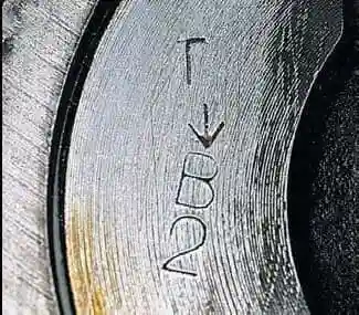
The arrow on the piston bottom when installing it in the cylinder must be directed towards the timing drive.
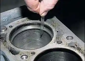
We check the gap in the piston ring lock with a set of flat feelers.
Lubricate the grooves on the pistons with engine oil. We install rings on the pistons
Before assembling the connecting rod and piston group, it is necessary to fit the fingers to the pistons and connecting rods.
For new parts, the class of the pin holes in the connecting rod and piston must match the class of the pin.
For used parts, for proper mating, it is necessary that the piston pin, lubricated with engine oil, enter the piston or connecting rod bore with hand force and not fall out of them when the pin is vertical.
To check the gap in the piston ring lock, insert the ring into the cylinder and align the ring with the piston head.
If the ring near the lock is marked TOP or TOP, then the ring is set with the mark up. The rings should turn freely in the grooves, without jamming.
Arrange the rings as follows:
- - the lock of the upper compression ring is oriented at an angle of 45 ° to the axis of the piston ring;
- -lock of the lower compression ring - at an angle of 180° to the axis of the lock of the upper ring;
- - oil scraper ring lock - at an angle of 90 ° to the axis of the lock of the upper compression ring (we place the expander joint on the side opposite to the lock).
Before installing the ShPG parts, we lubricate the cylinders, pistons with rings and connecting rod bearings with engine oil.
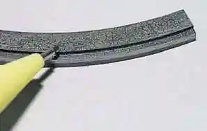
Set the lower compression ring with the groove down.
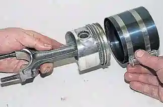
Before installing the piston into the cylinder, we put an adjustable mandrel on the piston and tighten the mandrel, compress the rings.
We install the piston with the connecting rod into the cylinder, orienting the piston with the arrow on its bottom towards the timing drive.
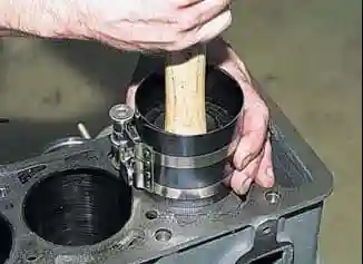
Push the piston into the cylinder with the hammer handle.
Having removed the mandrel, we send the piston into the cylinder with the hammer handle.
On the other side of the block, we look at the landing of the lower head of the connecting rod with an insert on the crankshaft neck.
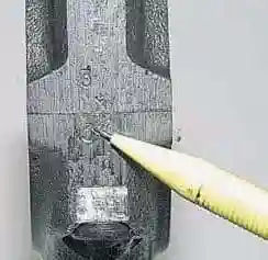
When installing the connecting rod caps, the numbers on the connecting rod and cap must match and be on the same side of the connecting rod
We tighten the connecting rod nuts with a torque of 43.32–53.51 Nm (4.42–5.4 kgf.m)
Running in the engine after repair
The repaired engine is subjected to bench tests (run-in) without load according to the following cycle:
- 750-800 min1 - 2 min
- 1000 min1 - 3 min
- 1500 min1 - 4 min
- 2000 min1 - 5 min
After benching and running the engine, check the following:
- - is there any leakage of coolant or fuel between mating parts, from pipeline connections and through gaskets;
- - oil pressure and whether there is oil leakage through the gaskets;
- - idling speed;
- - whether there are extraneous knocks.
If extraneous knocks or malfunctions are found, stop the engine, eliminate them, and then continue testing.
If oil leaks through the gasket between the cover and the cylinder head or through the gaskets between the engine oil sump, cylinder block and covers, tighten the mounting bolts to the recommended torque.
If the oil continues to leak, check that the gaskets are installed correctly and replace them if necessary.
Since the engine has not yet run in after the repair, and the friction of the working surfaces of new parts has a significant resistance to rotation, a certain period of running in is necessary.
This applies in particular to those engines on which pistons, connecting rod and main bearing shells have been replaced, crankshaft journals have been reground, and cylinders have been honed.
Therefore, during the break-in of a repaired engine, do not subject it to maximum loads.
The engine break-in must continue on the vehicle at the recommended driving speeds for the vehicle's break-in period.


