Remove
Remove the accessory drive belt.
Remove the crankshaft pulley.
Remove the right engine mount.
Remove the timing belt.
Remove the intake silencer.
Remove the air filter housing.
Remove the throttle body.
Remove the intake manifold.
Remove the camshaft seals from the timing side.
Remove the ignition coils.
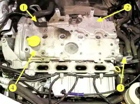
Disconnect hose 1, figure 1, crankcase ventilation from oil separator 2.
Unscrew the eight mounting bolts (replaceable head 8, extension, knob).
Pry off oil separator 2 from cylinder head cover 4 (flat screwdriver).
Remove the lifting eye 3 of the engine from the flywheel side on the cover 4 of the cylinder head (replacement head 16, ratchet wrench).
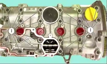
Unscrew the bolts 1, figure 2, fastening the cylinder head cover (replaceable head 8, extension, ratchet wrench).
Separate the cylinder head cover by pulling it up and tapping on the tabs with a bronze drift (technological drift).
Remove the cylinder head cover.
Installation
Clean the cylinder head and head cover from sealant residues.
Degrease the mating surfaces of the cylinder head and cylinder head cover (brush, white spirit).
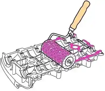
Apply Mastixo sealant with a paint roller, figure 3 (paint roller, Mastixo sealant).
Remove the sealant from the working surfaces of the bearings in the cylinder head cover (rags).
Install the cylinder head cover.
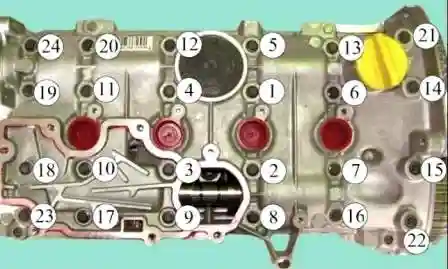
Install and tighten bolts 1…24 in the indicated order, Figure 4, fastening the cylinder head cover in several stages (replaceable head 8, extension, torque wrench):
- 1st stage - bolts 22, 23, 20 and 13 with a tightening torque of 8 Nm (0.8 kgf.m);
- 2nd stage - bolts 1 - 12, 14 - 19, 21 and 24 with a tightening torque of 15 Nm (1.5 kgf.m);
- 3rd step - loosen bolts 22, 23, 20 and 13;
- 4th stage - tighten bolts 22, 23, 20 and 13 with a tightening torque of 15 Nm (1.5 kgf.m).
Install the lifting eye 3, figure 1, of the engine on the flywheel side of the cylinder head cover. The tightening torque of the fastening bolt is 11 Nm (1.1 kgf.m) (replaceable head 16, torque wrench).
Clean oil separator 2 of sealant residue.
Degrease the mating surfaces of the cylinder head cover and oil separator (brush, white spirit).

Apply Mastixo sealant to the oil separator using a paint roller according to figure 5 (paint roller, Mastixo sealant).
Install the oil separator.
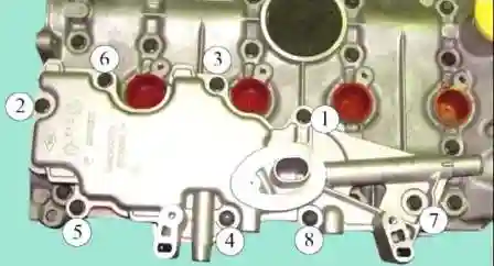
Install and tighten bolts 1…8, figure 6, of the oil separator fastenings in the indicated order.
Torque ki bolts for fastening the oil separator 15 Nm (1.5 kgf.m) (replaceable head 8, extension, torque wrench):
Connect hose 1, figure 1, crankcase ventilation to oil separator 2.
Install ignition coils.
Install the camshaft seals.
Install the intake manifold.
Install the throttle body.
Install the air filter housing.
Install the intake silencer.
Install the timing belt.
Install the right engine mount.
Install the crankshaft pulley.
Install the accessory drive belt.


