
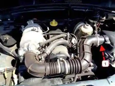
The mass air flow sensor on the VAZ-2123 engine is located between the air filter housing and the air supply hose to the throttle assembly
The sensor uses hot-wire anemometric flow measurement method, which is based on heat dissipation by a moving air stream.
When a current-heated thermistor (hot-wire anemometer transducer) is placed in a moving air medium, the heat dissipation by the air flow is the main factor affecting the heat transfer of the thermistor.
The resistance of the thermistor changes due to flow cooling, causing the resistor to act as an air flow sensor.
When the mass air flow sensor or its circuits fail, the "CHECK ENGINE" lamp lights up.
In this case, the controller calculates the mass air flow value from the crankshaft speed and throttle position.
The output signal of the DTV connected to the controller is a DC voltage in the range of 0.2 ... 4.8 V, the value of which depends on the temperature of the air passing through the sensor.
If a malfunction occurs in the DTV circuit, the controller stores its code in its memory and turns on the signaling device.
In this case, the controller replaces the sensor readings with a fixed air temperature value (20 °C).
Removing the mass air flow sensor

Remove the negative battery terminal

Use a Phillips screwdriver to loosen the clamp that secures the air hose to the mass air flow sensor

We move the yellow limiter of the retainer of the engine control system wiring block to the mass air flow sensor.

Press the latch and disconnect the wire block from the sensor

Using a 10 key, we unscrew the two bolts securing the mass air flow sensor

Remove the mass air flow sensor from the air filter housing

Marking of the MAF sensor
Installing the MAF
Before installing the sensor, we put a sealing sleeve on it until it stops.
Missing the sealing sleeve may cause engine malfunction.
Be careful when handling the sensor.
Do not allow foreign objects to get inside the sensor.
Damage to the sensor will cause the engine control system to malfunction.
It is forbidden to remove the sensitive element from the sensor housing, as this may lead to a change in its characteristics.
Install the sensor on the air filter and fixwe use two bolts.
Tightening torque of the bolts 3.0…5.0 Nm.
We attach the intake pipe hose to the sensor and fix it with a clamp.
Clamp screw torque 2.2…2.8 Nm.
We attach the wiring harness block to the sensor and snap the latch.
Table of air temperature sensor resistance versus intake air temperature:


")
")
")
")
")
")
")
")