Piston pins are installed with an interference fit in the upper heads of the connecting rods and rotate freely in the piston bosses, so heat the upper head of the connecting rod to a temperature of 250˚ C
When assembling, it is convenient to use the Mot574-22 kit and the Mot574-24 tool.
Disassembly and verification of the K4M engine SHPG was discussed in the article - " Dismantling and Troubleshooting of ShPG”.
Visually check the condition of the connecting rods (twisting and bending) and the cleanliness of the bearing surfaces of the connecting rod cap and crank head.
Use a 1500W hotplate to heat the top end of the connecting rods.
Place the upper connecting rod heads on the tile.
Make sure the top ends of the connecting rods are in full contact with the tile.
Place a piece of tin solder as a temperature indicator on each connecting rod head.
The melting point of tin solder is approximately 250°C.
Heat the top ends of the connecting rods until the solder melts.
Piston pin preparation
Check if the piston pins rotate freely in the bosses of the corresponding new pistons.
To install, use Drifters C13 and A13 from the Mot574-22 Collarless Piston Pin Kit or C13 and A13 from the Mot574-24 Collared Piston Pin Kit.

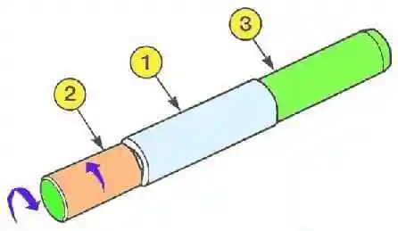
Install the piston pin (1) on the mounting mandrel (2) (see fig. 1).
- - Turn the mandrel (3) until the assembly is tightened.
- - Loosen the mandrel (2) a quarter of a turn.
Position of pistons in relation to connecting rods
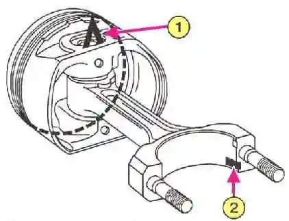
Pistons are marked with a "V" on the head, which should be on the flywheel side.

- - Position the piston head with the “V” mark up (see 1, fig. 2).
- - Direct the groove under the locking barb of the connecting rod bearing down (see 2, fig. 2).
Assembly

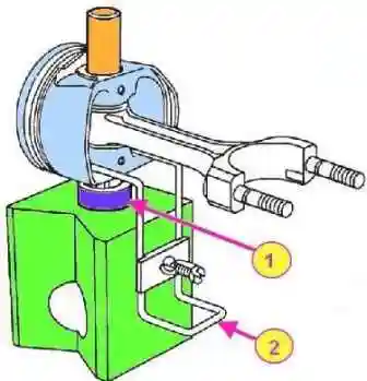
Mount the ring B10 (see 1, fig. 3) on the prism, the piston resting on the ring and fasten all the parts with a clamp (2).
Make sure the piston pin hole aligns with the B10 ring hole.
Lubricate the mandrel and piston pin with engine oil.
Leave the piston pin in the assembly and check if it rotates freely. Center the piston if necessary.
The following operations must be done quickly to prevent the connecting rod head from cooling down.
When the piece of solder melts, remove the solder.
Insert the centering mandrel into the piston,
Insert the correctly oriented connecting rod into the piston.
Quickly press the piston pin into the bottom of the tool until the centering mandrel stops.
Make sure that the piston pin does not protrude from the piston in any position of the connecting rod.
Installing piston rings
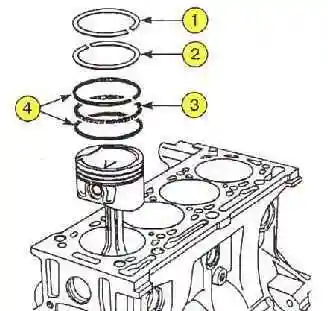
The piston rings are matched to the piston and must move freely in the piston grooves.
Observe the direction of installation of the rings (the “TOP” mark must be directed upwards).

Respect the position of the lock of each ring (see fig. 4). The locks of the compression rings must be rotated by 180˚, the locks of the parts of the oil scraper ring by 120˚.


