

The removal of the camshaft was covered in the article “Cylinder head removal”.
With excessive camshaft wear, the oil pressure in the engine may drop and valve knock may appear even with serviceable hydraulic tappets.
Dismantling and inspection of the camshaft
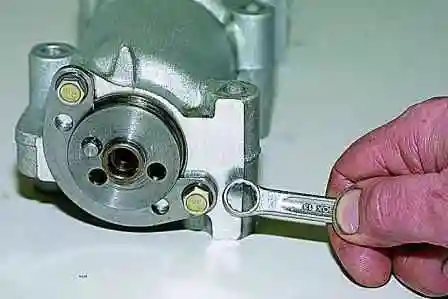
- We dismantle the camshaft bearing housing; to do this, using a 10 mm spanner, we unscrew the two bolts securing the camshaft thrust flange.
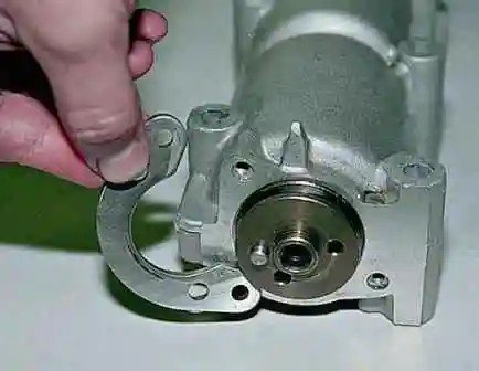
- We remove the thrust flange from the groove in the front support journal of the shaft.
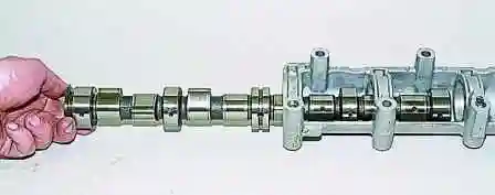
- We extract the camshaft from the bearing housing, sliding it forwards.
Note: When extracting the camshaft from the bearing housing, be careful — do not damage the surfaces of the supports for the camshaft journals with the sharp edges of the cams.
Inspection of the camshaft
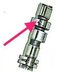
We inspect the camshaft. On the working surfaces of the journals, scoring, dents, scratches and aluminium smearing from the bearing housing are not permitted.
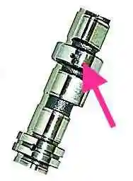
On the working surfaces of the cams, wear greater than 0.5 mm is not permitted, nor is scoring or faceted wear of the cams. Replace the shaft with the defects found.
Measuring the camshaft support journals
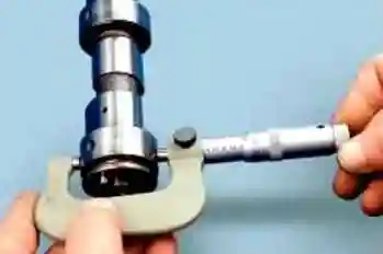
We measure the diameters of the shaft support journals. They must be (counting from the front):
- 1st journal — 45.915–45.931 mm;
- 2nd journal — 45.615–45.631 mm;
- 3rd journal — 45.315–45.331 mm;
- 4th journal — 45.015–45.031 mm;
- 5th journal — 43.415–43.431 mm.
Inspection of the bearing housing
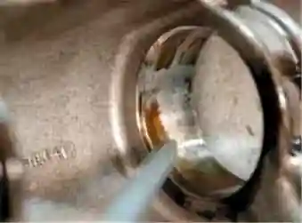
We inspect the camshaft bearing housing. Cracks in the housing are not permitted. On the working surfaces of the supports for the journals, scores, scratches, scoring and excessive wear are not permitted.

Measure the internal diameters of the camshaft housing supports. They must be (counting from the front):
- 1st support — 46.000–46.025 mm;
- 2nd support — 45.700–45.725 mm;
- 3rd support — 45.400–45.425 mm;
- 4th support — 45.100–45.125 mm;
- 5th support — 43.500–43.525 mm.
If the clearances between the shaft journals and the supports exceed 0.2 mm (limit wear), replace the housing and, if necessary, the camshaft.
Fitting the camshaft
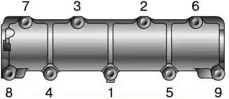
- Fit a new camshaft and bearing housing, as well as all the removed assemblies and parts, in the reverse order to removal.
- Before fitting the camshaft into the bearing housing, lubricate the working surfaces of the camshaft journals and cams with engine oil.
- Tighten the bearing housing mounting nuts in the sequence shown in Figure 9.
Nut tightening torque: 18.33–22.6 N·m (1.87–2.3 kgf·m).


