We remove the air intake elements during a major overhaul or in case of malfunctions.
Removing and installing turbocharger
Preparing the car for work. Disconnect the negative battery terminal.
Disconnect the intercooler hose.
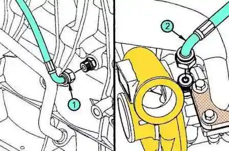
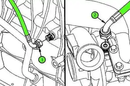
Remove the oil supply pipe.
Note: Use a wrench to keep the nipple from turning while loosening the nut.
- a) Remove the oil supply pipe from the cylinder block fitting (1).
- b) Remove the oil supply pipe from the bearing housing fitting (2).
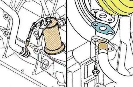
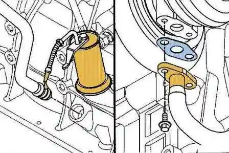
Remove the oil return pipe.
- a) Remove the oil return pipe mounting bolts.
- b) If necessary, remove the clamps from the oil return pipe connections.
- c) If necessary, pull the hose out of the fittings.
- d) Remove the oil return pipe fitting from the cylinder block.
- e) Remove the O-rings.
Remove the exhaust pipe.
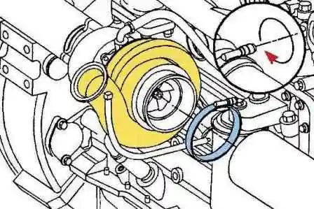
Disconnect the compressor inlet.
Remove the turbocharger.
Note: this assembly weighs more than 23 kg, please use a second person to avoid injury.
Attention: after removing the turbocharger, determine the type of gasket, some gaskets have a separator in the middle. Installing the wrong gasket will cause the turbocharger to malfunction.
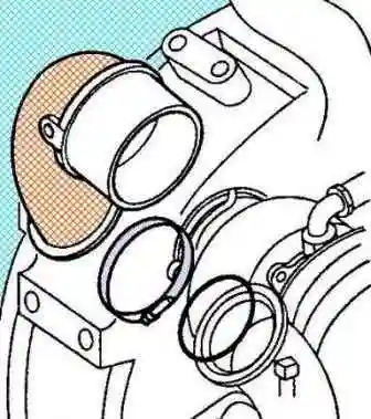
- a) Loosen the clamp and remove the compressor outlet with gasket.
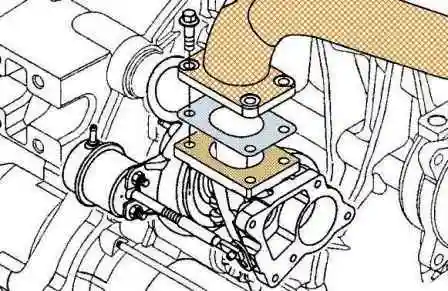
- b) Remove the four nuts securing the turbocharger.
- c) Remove the turbocharger and gasket. Note: Do not reuse turbocharger gasket.
Clean the surfaces of the turbocharger with solvent or steam to remove deposits and gasket residue.
Dry with compressed air.
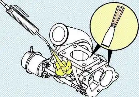
Check the turbocharger housing for cracks and damage.
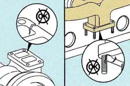
If the turbocharger has been severely damaged, check the boost system for debris, dirt, and oil.
Clean the air supply system, including the aftercooler.
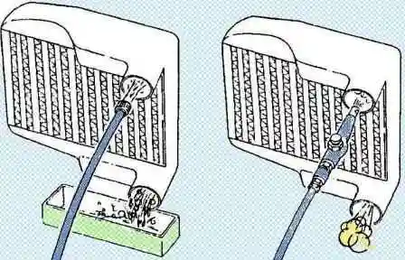
Installation
- a) Apply a thin coat of high temperature anti-seize compound to the turbocharger mounting studs.
- b) Install a new gasket of the same type as the previously removed one and install the turbocharger.
- c) Install and tighten the four fixing nuts.
Note: The specified tightening torques include the use of an anti-seize compound as a lubricant.
Tightening torque 24 Nm.
Install the oil return pipe
- a) Install the O-rings on the oil return pipe.
- b) Lubricate the O-rings with engine oil.
- c) Insert the drain line into its fitting. The O-rings must be fully seated in the hole.
- d) Connect Fit the oil return pipe flange with a new gasket to the bearing housing and tighten the bolts.
Tightening torque 10 Nm
Pour engine oil into the turbocharger.
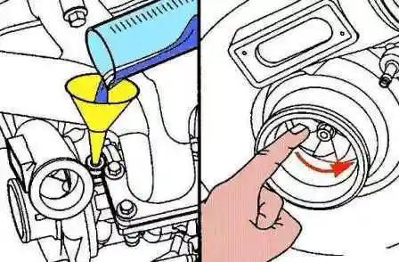
- a) Pour 60 - 90 ml of clean engine oil through the opening of the oil supply line to the turbocharger.
- b) Rotate the turbocharger wheel to allow oil to pass into the bearing housing.
Install the outlet pipe, band clamp and new O-ring at the turbocharger compressor outlet.
Tighten the clamp. Tightening torque 10 Nm
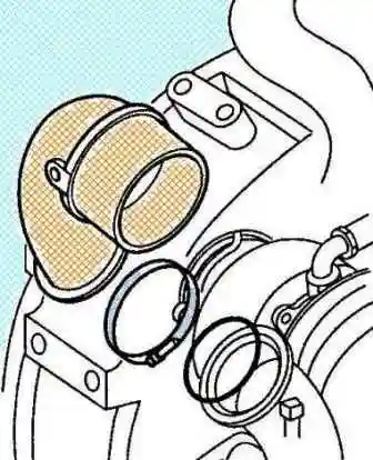
Connect the charge air cooler hoses.
Install and tighten the oil supply pipe
- a) Install new copper washers or O-rings.
- b) Connect the oil supply pipe to the cylinder block fitting (1) and to the bearing housing fitting (2).
- c) Tighten the fastening nuts. Tightening torque 28 Nm
Install the exhaust pipe.
Install the inlet pipe to the compressor.
Connect the batteries.
Start the engine and check for leaks.
Turbocharger bypass valve actuator
Initial checks
Check the flexible hose between the drive connection and the compressor housing for damage and tightness.
If damaged, replace the hose and clamps.
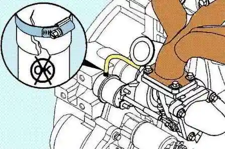
Check the support bracket, stem and actuator arm for damage.
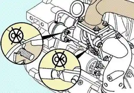
Expansion of the actuator stem hole will require replacement of the actuator.
If there is deformation in the support bracket, stem or bypass valve actuator arm, be sure to replace the bent part.
Withdrawal
Note: Before removing, mark the orientation of the bypass valve actuator housing fitting relative to the support bracket.
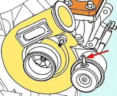
Remove the turbocharger.
Remove the bypass valve actuator.
- a) Remove the circlip from the control lever.
- b) Disconnect the hose from the bypass valve actuator body.
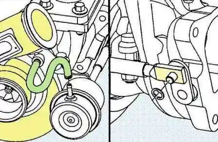
Disconnect the actuator stem from the bypass valve lever.
To do this, increase the pressure in the actuator housing until the stem begins to move.
Use an air pressure regulator fitted with a pressure gauge.
Disconnect the actuator stem from the bypass valve lever pin.
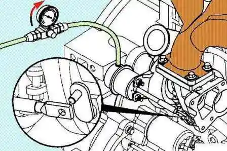
Note: If the actuator diaphragm is cracked and is not holding pressure, manually pull the stem against the actuator spring force to remove the stem from the bypass lever pin.
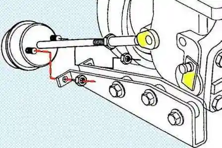
Loosen the drive housing mounting bolts, disconnect the air supply hose and remove the assembly from the support bracket.
Leak test
Disconnect the hose from the bypass valve actuator body.
Connect and secure the hose between the adjustable compressed air source and the drive.
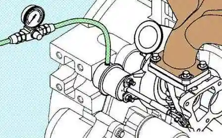
Increasing the pressure gradually to 300 kPa from a regulated compressed air supply to the actuator, check that the actuator stem moves.
Note: if the drive housing is in good condition, no air leakage noise should be heard.
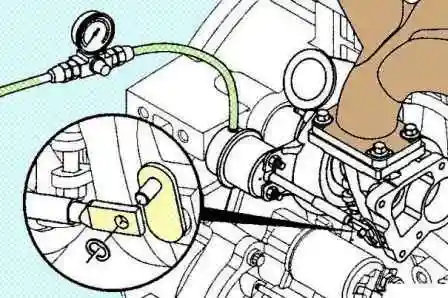
If the stem does not move, remove the retaining ring and disconnect the stem from the bypass valve lever pin.
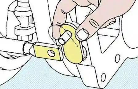
Inject pressurized air into the actuator housing and check if the stem moves.
If there is no movement, replace the bypass valve actuator.
If the actuator stem moves, shake the bypass valve lever and check for smooth movement.
If the bypass valve lever is sticking, spray some penetrating lubricant onto its hinge and try to wiggle and move the lever.
If you can't break it, replace the turbocharger.
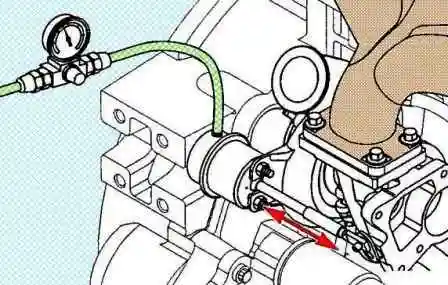
If you managed to move the lever and it began to move smoothly, connect the actuator stem and check its movement under the influence of air pressure.
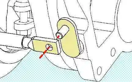
Installation
Install the linkage on the bypass valve lever pin.
Rotate the spacer so its ridge is visible and press the bypass valve lever against the stem, then lay the actuator along the support bracket.
Note: do not insert two studs into the holes at this stage.
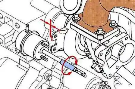
Adjust the actuator rod length by removing the actuator from the turbocharger.
By turning the stem end, position the actuator so that the studs can be inserted into the holes with a slight gap.
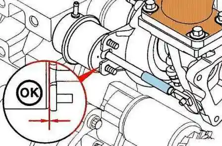
When properly adjusted, the lower part of the drive sits on the bracket with a gap of less than 0.5 mm.
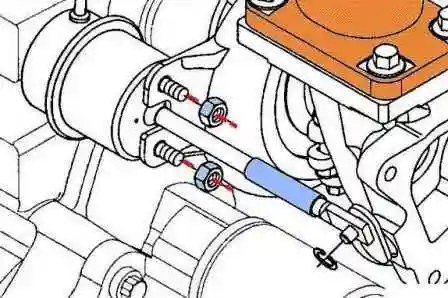
Install the drive mounting studs into the bracket holes.
Install the actuator stem onto the bypass valve lever pin. Install the circlip.
Tighten the mounting nuts. Tightening torque 8 Nm
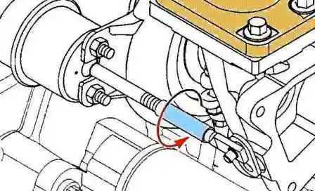
Tighten actuator stem jam nut, stem tip locked. Tightening torque 8 Nm
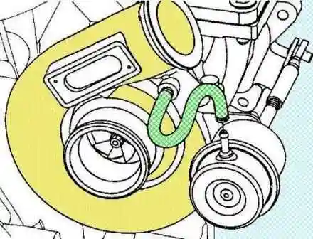
Connect a hose to the drive fitting, install a new clamp.
Intake manifold
Withdrawal
Disconnect the cable from the negative battery terminal.
Remove the charge air bypass line.
Remove the high pressure fuel pipes.
Remove the fuel supply hoses.
Remove the fuel accumulator.
Remove the air inlet adapter. Tightening torque 10 Nm
Remove the starting aid air intake heater.
Remove the boost pressure sensor and intake air temperature sensor assembly.
Drain the coolant.
Remove the coolant bypass tube with O-rings by removing the bolt. Tightening torque 24 Nm
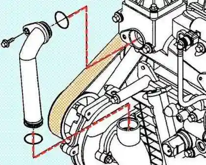
(Models with closed crankcase ventilation)
Remove the crankcase ventilation valve.
Remove the intake manifold.
Note: Be careful not to get any gasket residue or other foreign matter into the intake ports of the cylinder head.
- a) Remove the bolts securing the intake manifold to the cylinder head, remove the intake manifold.
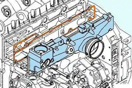
- b) Remove the gasket.
- c) Tape the channels in the cylinder head to prevent debris from entering them.
Installation
Install the intake manifold
Install the intake manifold and tighten the bolts. Apply sealant (#3824041) to bolt threads before installation.
Note: If the intake manifold is fitted with a gasket, replace the gasket.
If the intake manifold is installed with sealant, remove the old one and apply new RTV Heat Resistant Sealant (P/N 3164070). Tightening torque 24 Nm
Further installation is carried out in the reverse order of removal.
Start the engine and check for leaks.


