After we have prepared the nodes and the parts for assembling the cylinder block, we proceed to the assembly.
The assembly of a connecting rod with a piston is discussed in the article - "Piston assembly" .
Defection of the block and crankshaft was discussed in the article - "Preparation of the block and crankshaft '.
Installing piston cooling nozzles
New injectors must be carefully pressed into the holes of the cylinder block, this operation is complicated by the fact that the injectors are small and access to the mounting holes is difficult, so we recommend using tools.
Install the plate (2) of tool Mot.1494 on the cylinder block without tightening the two fastening bolts (1) (see fig. 1 and 2).
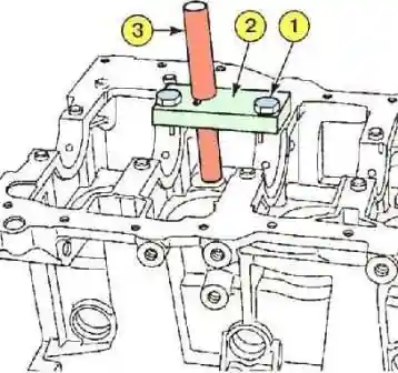
When installing the injectors of cylinders 1 and 3, the left hole of the support (1) figure 1 is used.
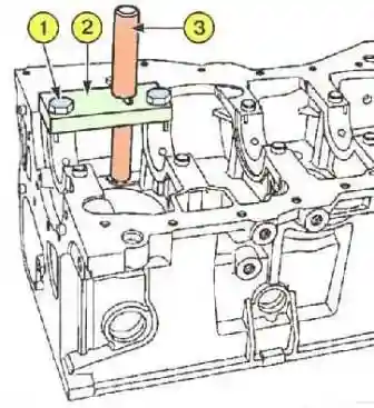
When installing the injectors of cylinders 2 and 4 - the right hole (picture 2).
Everything else is done in the same way.
Install the jig (3) into the plate (2). To center the plate, the end of the conductor must enter the hole for the nozzle.
- - Tighten the two mounting bolts (1).
- - Remove the jig (3).
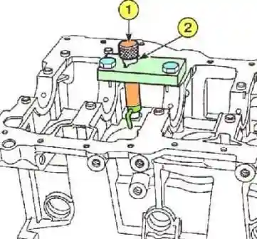
- Install the mandrel (1) instead of the jig (see Fig. 3). Insert the nozzle into the mandrel.
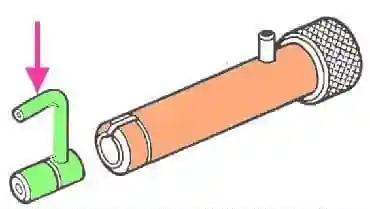
Note. Pay attention to the direction of installation of the nozzle, the nozzle tip must be directed towards the center of the cylinder (see the arrow, Fig. 4).
- Hit the mandrel with a hammer several times until the shoulder (see 2, Fig. 3) touches the mandrel with the support.
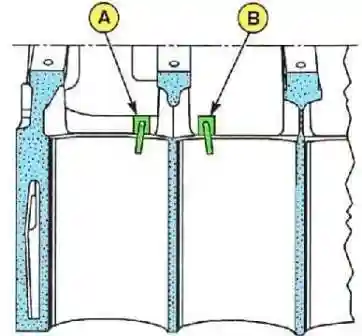
Check that the piston head cooling jets are correctly oriented.
The mark "A" corresponds to the injectors of cylinders 2 and 4, and the mark "B" corresponds to the injectors of cylinders 1 and 3 (see fig. 5).
Crankshaft bearing shells
It is not recommended to reuse crankshaft bearing shells.
During operation, hard wear particles interspersed in the soft layer of the liners, such liners subsequently accelerate the wear of the crankshaft journals.
Selection of root bearings
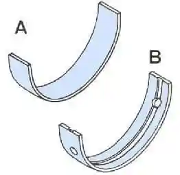
The engine is equipped with liners (see fig. 6) without orienting elements (without a guide "whisker").
Inserts are installed using tool Mot1493-01.
Main bearing shell dimensions

Installation
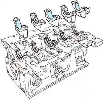
- - Install grooved liners in all beds of the cylinder block (see Fig. 7).
- - Install grooved shells in main bearing caps 2 and 4 and non-grooved shells in main bearing caps 1, 3 and 5.
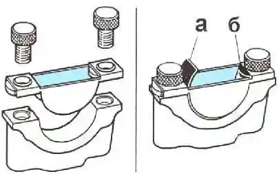
At the factory, a guide tool is used to install the main bearing shells (see fig. 8).
The liner is placed in the fixture and fed inward until the front edge of the liner stops against the protrusion of the fixture.
Checking the clearance in the main bearings
Never turn the crankshaft when checking the clearance.
- - Remove any remaining oil from the main journals and bearings of the cylinder block.
- - Install the crankshaft and crankshaft thrust washers on the 3rd support (with grooves towards the crankshaft cheeks).
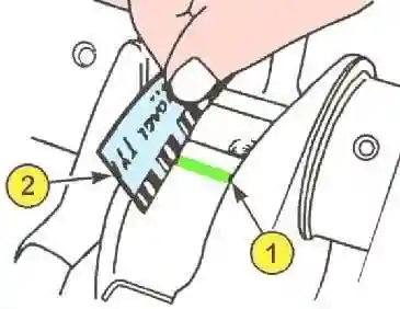
- - Cut a few pieces of calibrated plastic wire from the coil (see 1, fig. 9).
- - Lay the wire along the axis of the main journals of the crankshaft (outside the area of the bearing lubrication holes).
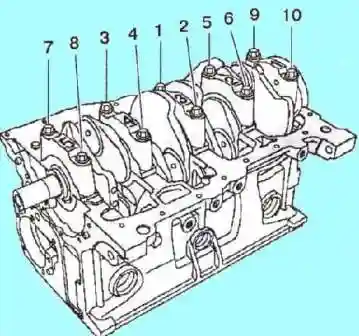
- - Install the crankshaft main bearing caps in their original places (see Fig. 10).
- - Properly tighten the crankshaft main bearing cap bolts in the order shown.
- In this case, the plastic wire will be crushed - it will occupy the entire gap between the liner and the crankshaft journal.
- - Remove the main bearing caps and take the crankshaft out of bed.
- - According to the width of the flattened calibrated wire, using a regular template, determine the gap between the liners and the main journals (2) (see Fig. 10).
- - Check the gap, which should be 0.027-0.054 mm.
- - Clean the crankshaft and the main bearing shells from the remnants of the calibrated wire.
Checking the axial clearance of the crankshaft
- - Lubricate the crankshaft main bearing shells with engine oil. Only the surface facing the shaft journal is lubricated.
- - install the crankshaft.
- - Check the presence of thrust half rings on the 3rd support (the grooves of the half rings should be directed towards the cheeks of the crankshaft).
The seating surfaces of the cylinder block support and No. 1 main bearing cap must be clean, dry and free of oil.
Excess sealant will be squeezed out when parts are tightened.
If drops of hardened sealant get into oil or coolant, it can clog some components and assemblies (engine, radiator, etc.).
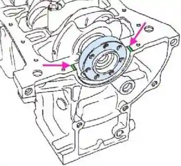
- - Apply RHODORSEAL 5661 in strips 1 mm wide (see arrow, fig. 11).
- - Install the crankshaft main bearing caps by installing cap No. 1 on the flywheel side (see fig. 10).
- - Tighten the crankshaft main bearing cap bolts in the order shown.
- - Check the axial movement of the crankshaft, which should be:
- - new half rings, mm. 0.045-0.252;
- - old half rings, mm. 0.045-0.852.
- - Check the ease of rotation of the crankshaft.
Installing the connecting rod bearing shells
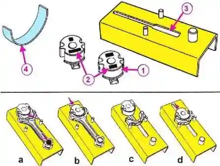
The motor is equipped with smooth bushings without guide barbs (see 4, fig. 12). The bushings are installed using tool Mot1492.
- - Select the mandrel (1) according to the engine model (see the marks (2) for the engine model).
- - Install the mandrel in the groove of the body (3).
- - Fit the connecting rod to tool Mot. 1492.
- - Put the upper head of the connecting rod to the support pin and press the connecting rod in the direction of the arrow (a).
- - Install the insert on the mandrel.
- - Feed the mandrel with the bushing into the lower end of the connecting rod (b).
- - Remove the mandrel from the connecting rod head and repeat the operations with the remaining connecting rods.
- - Install the connecting rod cap onto the housing pins.
- - Install the connecting rod bearing on the mandrel (c).
- - Feed the mandrel with the insert into the connecting rod cap (d).
- - Remove the mandrel from the connecting rod cap and assemble the rest of the connecting rod caps in the same way.
Assembly of connecting rods with pistons and installation of rings, discussed in the article - "Assembly of the SHPG"
Tightening torques for fasteners
Knot - Tightening torque, Nm
- Crankshaft main bearing cap bolts 20+62˚±4˚
- Connecting rod cap bolts 20+40˚±6˚
- Water pump cover bolts 15
- Water pump bolts 17
- Water pump pulley bolts 20
- Screw bolt 50
- Oil separator and oil pump bolts 24
- Sump bolts 14
- Oil level sensor 16-24
- Oil filter nipple (without cooler) 10-20
- Oil filter nipple (with cooler) 55-60
- Knock sensor 20
- Oil pressure sensor 30
- Oil filter 10-14
- Coolant pipe mounting bolts 9
- 50-55 conventional flywheel mounting bolts
- Dual damping flywheel mounting bolts 18-22,+50˚±6˚
- M6 bolts fastening the clutch cover 15±10%
- M7 bolts fastening the clutch cover 20±10%
- M8 bolts fastening the clutch cover 25±10%
Continuation of the article on the assembly of the K4M cylinder block in the next article.


