We install the cylinder block on the stand for disassembly and assembly of units
We install on the crankshaft 1, figure 1, pin 4 the centering disk for setting the position of the crankshaft
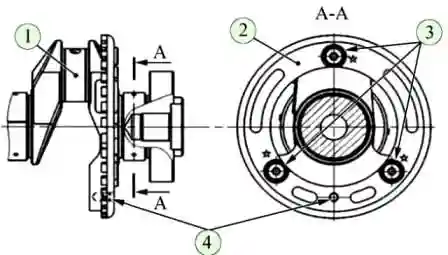
We twist and tighten the three bolts 3 fastening the drive disk.
The tightening torque of the disc mounting bolts is 20-24 Nm (2.0-2.4 kgcm)
Remove the centering pin from the crankshaft
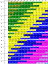
We select the crankshaft main bearing shells according to the classification of the crankshaft main journals and bearings in the cylinder block in accordance with table 1
The color in the table indicates the marking of the liner on its end.
The color of the marking corresponds to a certain bearing class, which must be installed depending on the diameter class of the main journals and the diameter class of the holes in the supports.
The upper part of the table shows the diameter classes of the holes in the cylinder block bearings, the left part shows the diameter classes of the crankshaft main journals.
Abbreviations shown in Table 1:
- UPR - an insert installed in the cylinder block support;
- LWR is a bushing that is installed in the main bearing cap.
Install the grooved liners in the cylinder block supports.
Aligning the new bearing shells with the grooves on the cylinder block, aligning the groove of the bearing shell with the groove of the bearing
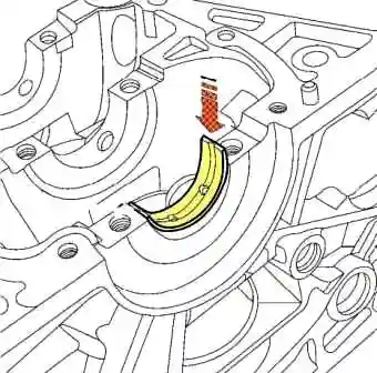
Install the bearing shells flush with the support, as shown in Figure 2, and press on it from the back in order to set the bearing flush with the support
We adjust the position of the liners so that they are located in the center of the cylinder block supports
Install liners without grooves in the cylinder covers
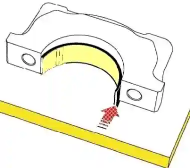
Set the liners flush with the surface of the main bearing cap, as shown in Figure 3, and slide it to the opposite side until it aligns with the cap
In the same way, install the rest of the liners
We adjust the position of the liners so that they are located in the center of the cylinder covers
We install the crankshaft thrust half-rings in the sockets of the third bearing of the cylinder block, aligning the antennae of the half-rings with grooves 1, Figure 4, supports.
In this case, the grooves of the 2 half-rings must be on the side of the crankshaft
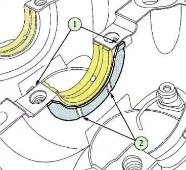
Lubricate with engine oil the surfaces of the main bearing shells and thrust half rings of the crankshaft in contact with the crankshaft
Install the crankshaft in the cylinder block
We install the main bearing caps assembly with liners on the cylinder block in accordance with their numbering
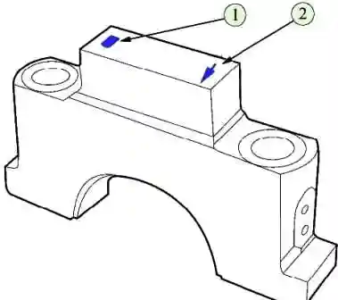
The numbering of the caps starts from the timing side.
The arrows on the covers should point towards the timing drive
Numbering and arrows are located on the surfaces of the cap bosses, as shown in Figure 5
Install and tighten new main bearing cap bolts
We tighten the bolts of the main bearing caps in two steps (head interchangeable TORX E14, knob, extension, torque wrench, head for measuring the angle of rotation):
- - tighten the bolts with a tightening torque of 30…35 Nm (3.0…3.5 kgf.m);
- - tighten the bolts by an angle of 60º…65º.
After that, we check the rotation of the crankshaft. The shaft should rotate from the force of the hand freely and without jamming.
In case of tight rotation or jamming, it is necessary to remove the crankshaft and repeat the operation to select the set of liners.
Checking the axial clearance of the crankshaft
Install the indicator stand on the cylinder block as shown.
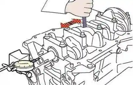
Let the measuring rod of the indicator on the crankshaft flange and set the indicator scale to zero.
Moving the crankshaft with screwdrivers, measure the axial clearance of the shaft.
The axial clearance of the crankshaft should be within 0.1 ... 0.3 mm.
If the axial clearance is more than 0.3 mm, adjust the clearance by replacing the thrust half rings (tripod ShM-PV-8, indicator ICh-10, flat screwdriver - 2 pcs., micrometer type MK 25-1).
Check the clearances in height between the piston grooves and rings and the clearances in the locks of the rings.
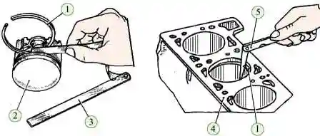
The gap between the ring 1, figure, and the wall of the piston groove 2 for the upper compression ring should be 0.06 ... 0.15 mm, for the second - 0.03 ... 0.07 mm, for the oil scraper ring - 0.045 ... 0.125 mm .
Measure the gap at three points at an angle of 120º to each other.
The gap in the lock of the upper compression ring should be 0.2 ... 0.3 mm, for the second - 0.35 ... 0.50 mm, for the oil scraper ring - 0.20 ... 0.45 mm.
Piston rings with a gap in the lock exceeding the maximum value should be replaced; if the gap is less than the minimum value, it is allowed to file the butt surfaces of the ring (a set of probes, a needle file).
Assembly of the connecting rod and piston group
We install the connecting rod caps on the connecting rods and tighten them without tightening the mounting bolts
We place the connecting rods in an electric oven heated to 240º.
The upper heads of the connecting rods must point into the oven.
The heating time of the connecting rods in the oven is at least 15 minutes
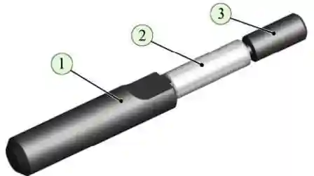
We install fixture 1 on the roller, drawing, piston pin 2 and guide 3
We remove the heated connecting rod from the electric furnace, quickly fix it to the lower head in a vice so that the installation mark 1, figure, is located on the installation side of the piston pin
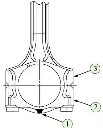
We put the piston on the connecting rod head so that the alignment mark (the point on the piston bottom) is located on the installation side of the piston pin.
Combine the hole for the piston pin with the hole of the upper head of the connecting rod and insert the tool assembly with the piston pin into the hole until the mandrel shoulders stop against the piston boss.
In this case, the piston should be pressed by the boss against the upper head of the connecting rod against the direction of pressing the pin.
Repeat this operation for the rest of the pistons.
Next, unscrew the mounting bolts and remove the connecting rod caps
After that, you need to assemble the connecting rod bearings according to the classification of the connecting rod journals of the crankshaft and the holes in the lower heads of the connecting rods in accordance with table 2
The color in the table indicates the marking of the liner on its end.
The color of the marking corresponds to a certain bearing class, which must be installed depending on the diameter class of the connecting rod journals and the diameter class of the holes in the lower headsatunov.
The upper part of the table shows the classes of diameters of the holes in the lower heads of the connecting rods, and the classes of diameters of the connecting rod journals of the crankshaft are indicated in the left part.
Abbreviations shown in the table:
- UPR - insert installed in the connecting rod;
- LWR - an insert installed in the connecting rod cap.
Install piston rings on the pistons
Set the lower compression ring with the scraper down
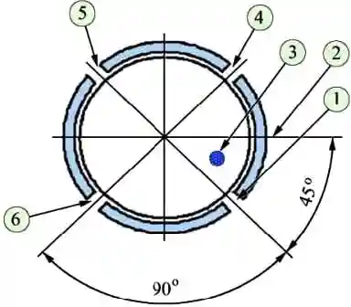
The orientation of the piston ring locks is shown in the figure
Install in the connecting rod with a hole flush with the plane of the connector, as shown in the figure
Move the insert from the opposite side to align with the plane of the connector
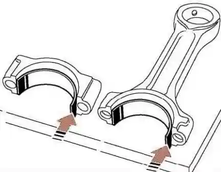
We adjust the position of the liner so that the hole in the liner completely coincides with the hole in the connecting rod and the distance from the side surfaces of the connecting rod to the liner on each side is the same
Repeat this operation to install the liners for the remaining connecting rods
Install the liner without a hole in the connecting rod cover flush with the connector plane, as shown in the figure.
Move the insert from the opposite side to align with the plane of the connector
We adjust the position of the liner so that the distance from the side surfaces of the cover to the liner on each side is the same
Repeat the installation operations for the inserts for the rest of the covers
Lubricate cylinders, liners, piston skirts, crankshaft crankpins with engine oil
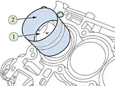
We install fixture 2 on piston 1, drawing, fixture 2 so that the piston skirt protrudes from the fixture by about 1 cm
We compress the piston rings and install the piston assembly with the connecting rod into the cylinder, in accordance with the marking.
The mark on the piston crown must face the timing drive.
Repeat the operations for the remaining three pistons.
Install the connecting rod caps in accordance with the markings.
The markings on the cap and on the connecting rod must match the cylinder number.
We install and tighten the new connecting rod cap bolts.
Tighten the bolts of the main bearing caps in two steps (replacement head 11, knob, extension, torque wrench, head for measuring the angle of rotation):
- - tighten the bolts with a tightening torque of 19…20 Nm (1.9…2.0 kgf.m);
- - tighten the bolts by an angle of 60º…65º.
Install a new cylinder block booster O-ring and two dowel pins into the cylinder block.
Protrusion of pins from the cylinder block - 9…11 mm
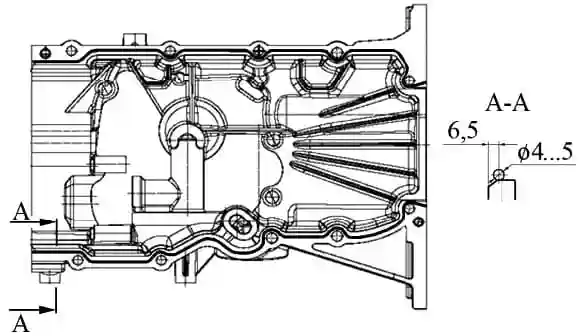
Apply a sealant bead with a diameter of 4…5 mm, Figure 6, on the plane of the connector of the cylinder block amplifier with the cylinder block at a distance of 6.5 mm from the inner edge of the amplifier (TV 1217 L silicone sealant, consumption rate - 14 g).
Attention! The time of open exposure of the sealant is not more than 5 minutes.
Mount the cylinder block booster to the cylinder block and secure with ten bolts in the order shown in figure 7
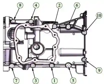
The tightening torque of the bolts is 21.0…29.0 N.m (2.1…2.9 kgf.m)
Remove any remaining sealant
Apply a sealant bead with a diameter of 4…5 mm, Figure 8, on the parting plane of the oil sump cover with the cylinder block reinforcement at a distance of 6.5 mm from the inside the lower edge of the amplifier (silicone sealant TV1217 L, consumption rate - 8 g).
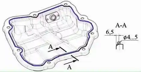
Attention! The time of open exposure of the sealant is not more than 5 minutes.
After that, install the assembled cylinder head, as indicated in the article "Disassembly and H4M engine cylinder head repair»
Install the oil pump assembly with rings on the engine and secure with three bolts.
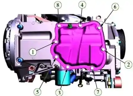
The tightening torque of the oil pump mounting bolts is 21 ... 29 Nm (2.1 ... 2.9 kgf.m)
Install the water pump with a new gasket on the engine and install and tighten the four mounting bolts.
The tightening torque of the water pump mounting bolts is 21 ... 29 Nm (2.1 ... 2.9 kgf.m) (replaceable head 10, knob, extension, torque wrench).
Install the drive pulley on the water pump, turn and tighten the three bolts securing the water pump pulley, holding the pulley with a screwdriver.
The tightening torque of the water pump pulley bolts is 7.0 ... 7.5 Nm (0.70 ... 0.75 kgf.m) (flat screwdriver, interchangeable head 10, knob, torque wrench).
Lubricate the lip of the crankshaft rear oil seal with engine oil and install the oil seal but the crankshaft flange
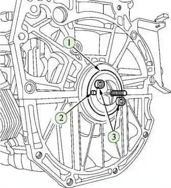
Install the guide sleeve 9, figure, tools for installing the rear oil seal on the crankshaft, aligning the hole in the sleeve with the pin 2 (tool 7711381919).
Fix the bushing on the crankshaft with two bolts 3 fastening the flywheel (replaceable head TORX E20, crank)
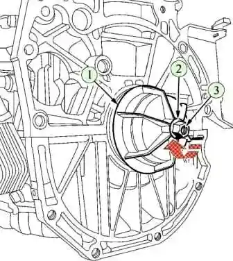
Install cover 1, figure 10, tools, washer 2 and nut 3 on the guide bushing.
Apply a soapy solution to the seating surface of the stuffing box and press the stuffing box into the cylinder block, turning the nut until cover 1 comes into contact with the cylinder block (replaceable head 17, knob).
Remove the oil seal installer from the crankshaft.
Install the coolant outlet pipe with a new gasket on the engine and secure with seven bolts.
The tightening torque of the nozzle mounting bolts is 21…29 Nm (2.1…2.9 kgf.m)
Put the outlet coolant temperature sensor into the pipe.
The tightening torque of the coolant temperature sensor is 25 ... 35 Nm (2.5 ... 3.5 kgf.m)
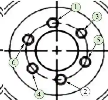
Install the flywheel on the crankshaft and tighten the new flywheel mounting bolts (replaceable head TORX E20, crank).
Install the flywheel retainer on the engine and tighten the flywheel mounting bolts in the sequence shown in the figure.
The tightening torque of the bolts is 103…112 Nm (10.3…11.2 kgf.m)
Remove the flywheel retainer.
Screw a new phaser oil filter with a washer into the cylinder head.
Filter tightening torque - 36.0 ... 43.0 Nm (3.6 ... 4.3 kgf.m) (replaceable head 8 for an internal hexagon, knob and extension, torque wrench).
Lubricate the O-ring of the dephaser solenoid valve with engine oil, install the valve in the cylinder head and secure with a bolt.
The tightening torque of the valve mounting bolt is 8.0…12.0 Nm (0.8…1.2 kgf.m)
Install the thermostat valve in the cylinder block, with the mark on the valve facing outward and located at the top of the vertical axis.
Set Roofs thermostat housing and secure it with two bolts. Tightening torque of the thermostat cover bolts - 16 ... 17 Nm (1.6 ... 1.7 kgf.m)
Install the clip for the oil level indicator tube.
Lubricate the O-ring of the oil gauge tube and install the tube in the cylinder block
Fix the tube on the thermostat cover.
Install the oil level gauge.
Lubricate the O-ring of the oil filter, screw in the oil filter until it touches the O-ring of the cylinder block and tighten the filter ¾ turn by hand
Apply sealant to the threaded part of the oil pressure sensor, wrap the sensor into the cylinder block.
Sensor tightening torque - 12…17 Nm (1.2…1.7 kgf.m)
Install the knock sensor on the cylinder block and secure with a bolt.
In this case, the sensor connector must be directed towards the flywheel.
The tightening torque of the sensor mounting bolt is 20 ... 25 Nm (2.0 ... 2.5 kgf.m) (replaceable head 10, knob, extension, torque wrench).
Lubricate the sealing ring of the crankshaft position sensor with engine oil, install the sensor on the engine and secure with a bolt.
The tightening torque of the crankshaft position sensor mounting bolt is 6.0 ... 8.0 Nm (0.6 ... 0.8 kgf.m)
Install the key and timing sprocket (hammer) on the crankshaft.
Install the oil pump sprocket onto the oil pump shaft, screw in and tighten the sprocket mounting nut.
The tightening torque of the oil pump sprocket nut is 21 ... 29 Nm (2.1 ... 2.9 kgf.m) (ring wrench 10, interchangeable head TORX E8, knob, interchangeable insert 10, torque wrench).</ p>
Install a new oil pump drive chain on the timing and oil pump sprockets.
Install a new tensioner 1, Figure 14, of the oil pump drive chain on the guide pin and insert the tendril of the spring 2 of the tensioner into the hole on the cylinder block.
Lubricate the bearing surfaces of the camshafts and install the camshafts in the cylinder head.
Install the camshaft with oil ducts on the flange on the intake side
Lubricate the camshaft journals, install the camshaft covers and intake cover bolts
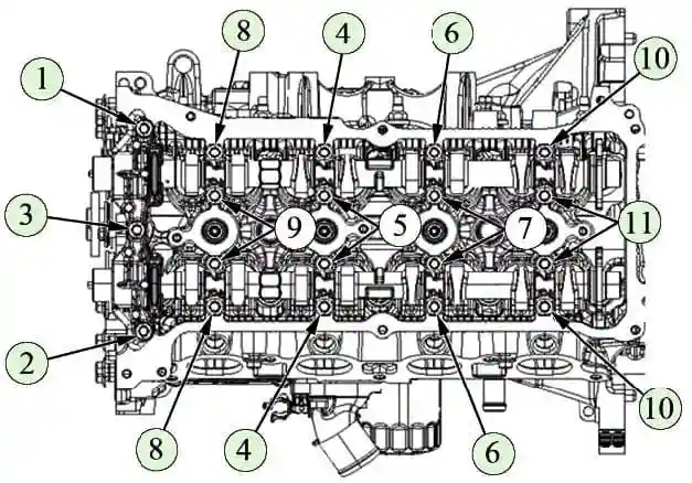
Turn and tighten the bolts of the covers in the sequence shown in Figure 11.
Tighten the camshaft bearing cap bolts in two steps:
- - tighten the bolts with a tightening torque of 5.0 Nm;
- - tighten the bolts with a tightening torque of 9.0…11.0 Nm.
Turn the camshafts so that the locating pins are in the upper position (wrench 22).
Turn the crankshaft with the key to the top position.
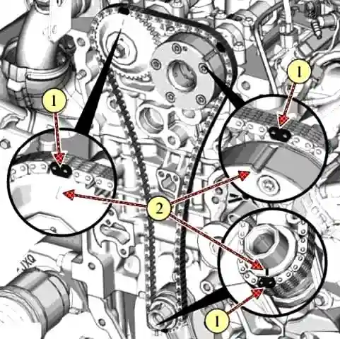
Install a new timing chain on the phase regulator so that mark 2, figure 12, of the phase regulator is located in the middle of the orange link 1 of the chain.
Install the phase shifter with chain onto the intake camshaft and secure with the bolt.
Do not tighten the bolt completely (wrench 22, interchangeable head 13, knob and extension).
Attention! When installing the phase regulator, be sure to align the mounting hole on the phase regulator hub, located between the two oil channels, with the alignment pin on the camshaft.
Attention! After installing the phase regulator from spare parts, remove the transport pin from it.
Install the chain on the camshaft sprocket so that mark 2, drawing, sprockets is located in the middle of the orange link 1 of the chain.
Install the sprocket onto the exhaust camshaft, aligning the mounting hole with the pin, and secure with the bolt. Do not completely tighten the bolt
Install the timing chain on the crankshaft sprocket so that the mark 2, figure 12, is located in the middle of the yellow link 2 of the chain.
Install the flywheel lock on the engine and lock the flywheel.
Mount the new chain guide to the engine and secure with two bolts. The tightening torque of the damper mounting bolts is 21…29 Nm (2.1…2.9 kgf.m)
Install a new chain tensioner shoe on the guide pin in the cylinder block.
Mount the new chain tensioner to the engine and secure with two bolts. Tightening torque of chain tensioner mounting bolts – 8.0…12.0 N.m (0.8…1.2 kgf.m).
Remove the transport pin from the tensioner body (replaceable head 8, knob, torque wrench, pliers).
Tighten the bolts of the phase regulator and camshaft sprocket.
The tightening torque of the mounting bolts is 74 ... 83 Nm (7.4 ... 8.3 kgf.m)
Remove the flywheel retainer from the engine.
Install the auxiliary drive pulley bolt into the crankshaft, turn the crankshaft one turn clockwise and check that the marks on the chain match the marks on the sprockets and on the phase regulator.
If the marks do not match, repeat the operations for installing the chain (replaceable head 19, knob).
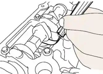
Check the clearances in the valve drive mechanism by turning the crankshaft so that the camshaft cam being checked points upwards, as shown in the figure.
The allowable clearance should be: for intake valves - 0.26 ... 0.34 mm, for exhaust valves - 0.29 ... 0.37 mm.
If the gap deviates from the specified value, remove the camshafts and replace the corresponding tappets.
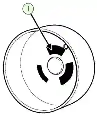
Depending on the thickness, the pushers are supplied in several classes of spare parts.
Table - Classification of pushers
|
Item No. |
Identity number |
Thickness, mm |
|---|---|---|
|
1 |
300 |
3.00 |
|
2 |
302 |
3.02 |
|
3 |
304 |
3.04 |
|
4 |
306 |
3.06 |
|
5 |
308 |
3.08 |
|
6 |
310 |
3.10 |
|
7 |
312 |
3,12 |
|
8 |
314 |
3.14 |
|
9 |
316 |
3.16 |
|
10 |
318 |
3.18 |
|
11 |
320 |
3.20 |
|
12 |
322 |
3.22 |
|
13 |
324 |
3.24 |
|
14 |
326 |
3.26 |
|
15 |
328 |
3.28 |
|
16 |
330 |
3.30 |
|
17 |
332 |
3.32 |
|
18 |
334 |
3.34 |
|
19 |
336 |
3.36 |
|
20 |
338 |
3.38 |
|
21 |
340 |
3.40 |
|
22 |
342 |
3.42 |
|
23 |
344 |
3.44 |
|
24 |
346 |
3.46 |
|
25 |
348 |
3.48 |
|
26 |
350 |
3.50 |
The classification of pushers is shown in the table.
The pusher class is indicated on the inner surface of the pusher, drawing.
After replacing the tappets, install the camshafts and timing mechanism according to the above procedure.
Apply two bead sealant along the split line of the cylinder block with the cylinder head and two bead sealant along the split line of the cylinder block with the timing side reinforcement
Install the timing pins of the timing cover on the engine. The protrusion of the pins above the mating surface - 10±0.5mm
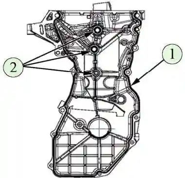
Apply sealant to the surface of the timing cover mating with the cylinder block, as shown in the figure, with a roller with a diameter of 3.5 mm (sealant TV 1217L, consumption rate - 14 g).
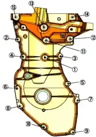
Install the cover and fasten it with bolts in the following order (interchangeable heads 8, 10, 13, knob, torque wrenches):
- - pre-tighten bolts 3, 2, 8 and 7, Figure 14. Bolt tightening torque - 8.0 N.m (0.8 kgf.m);
- - finally tighten bolts 1, 2, 3, 4, 5, 6, 7, 8, 11, 12, 13, 14, 15, 9 and 10. Tightening torques:
- - bolt 1 - 5…8 N.m (0.5…0.8 kgf.m);
- - bolts 2, 3, 4, 5, 6, 7, 8, 9 and 10 - 21 ... 29 N.m (2.1 ... 2.9 kgf.m);
- - bolts 11, 12, 13, 14 and 15 - 47 ... 63 N.m (4.7 ... 6.3 kgf.m).
Install the new front crankshaft oil seal on the drift (drill 77 11 381 918 for installing the front crankshaft oil seal).
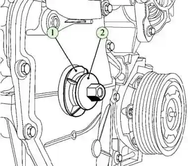
Apply a soapy solution to the seating surface of the oil seal, install mandrel 1, figure, with an oil seal on the crankshaft, tighten bolt 2 for fastening the auxiliary drive pulley until the mandrel comes into contact with the timing drive cover (replaceable head 19, knob).
Remove the bolt and remove the mandrel.
Press the two centering pins of the cylinder head cover into the cylinder head.
Protrusion of pins above the mating surface of the cylinder head 7 + 1 mm
Install a new gasket on the cylinder head cover.
Apply two strips of sealant 20 mm long at the junction of the cylinder head with the timing cover in the upper part (sealant TV 1217L, consumption rate - 3 g).
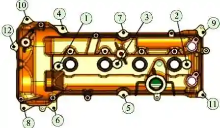
Install the cylinder head cover with gasket on the cylinder head, cover bolts and tighten the bolts in the order shown in Figure 15.
The tightening torque of the cylinder head cover bolts is 8.0 ... 12.0 Nm (0.8 ... 1.2 kgf.m)
Install the phase sensor into the cylinder head cover and secure with a bolt.
The tightening torque of the phase sensor mounting bolt is 9.0 ... 12.0 Nm (0.9 ... 1.2 kgf.m)
Replace the spark plugs. Spark plug tightening torque - 21.0 ... 27.0 Nm (2.1 ... 2.7 kgf.m)
Install the ignition coils and bolt to the cylinder head cover.
The tightening torque of the ignition coil mounting bolts is 9.0 ... 12.0 Nm (0.9 ... 1.2 kgf.m)
Install the fuel rail assembly with injectors on the engine and secure with two bolts.
The tightening torque of the fuel rail mounting bolts is 21.0 ... 29.0 Nm (2.1 ... 2.9 kgf.m)
Connect the connectors of the injector wiring harness to the injectors.
Install a protective fuel shield amps and fix it with two bolts to the cylinder head cover and two bolts to the fuel rail.
The tightening torque of the screen-wound bolts to the cylinder head cover is 21.0 ... 29.0 Nm (2.1 ... 2.9 kgf.m), the tightening torque of the screen-to-fuel rail bolts is 10.0 ... 13 .0 Nm (1.0…1.3 kgf.m)
Install the wiring harness bracket on the engine and bolt to the cylinder head cover.
The tightening torque of the bracket fastening bolt is 8.0…12.0 Nm. (0.8 ... 1.2 kgf.m) (replaceable head 8, knob, torque wrench).
Connect the wiring harness connectors to the ignition coils and secure the harness to the cylinder head cover and bracket.
Install the intake module with new gaskets on the engine and bolt it to the cylinder head and cylinder head cover.
The tightening torque of the intake module fastening bolts is 7…15 Nm (0.7…1.5 kgf.m)
Install the crankcase ventilation tube and secure with clamps
Install throttle body heating hoses and secure with clamps
Install the flywheel lock on the engine and lock the flywheel
Lubricate the seating surface of the accessory drive pulley under the oil seal with engine oil, install the pulley on the crankshaft and secure with a new bolt.
The tightening torque of the pulley mounting bolt is 30.0 ... 40.0 Nm. (3.0…4.0) kgf.m. After tightening, tighten the bolt by an angle of 60º…66º
Remove the flywheel retainer.
Mount the accessory bracket to the engine and secure with four bolts.
The tightening torque of the bracket fastening bolts is 21.0…29.0 Nm (2.1…2.9 kgf.m)
Install the lower heat shield on the exhaust manifold and secure with bolts.
The tightening torque of the screen mounting bolts is 10.0 ... 13.0 Nm (1.0 ... 1.3 kgf.m) (replaceable head 10, knob and extension, torque wrench).
Install a new exhaust manifold gasket on the engine, manifold and secure with nuts.
The tightening torque of the exhaust manifold mounting nuts is 30.0 ... 40.0 Nm (3.0 ... 4.0 kgf.m)
Screw the oxygen sensor into the exhaust manifold. Tightening torque of the oxygen sensor - 38 ... 50 Nm (3.8 ... 5.0 kgf.m)
Install the upper heat shield on the exhaust manifold and fasten it with bolts.
The tightening torque of the screen mounting bolts is 10.0 ... 13.0 Nm (1.0 ... 1.3 kgf.m) (replaceable head 10, knob and extension, torque wrench).
Mount the alternator to the accessory bracket and secure with two bolts.
The tightening torque of the generator mounting bolts is 21.0-29.0 Nm (2.1-2.9 kgf.m)
Mount the A/C compressor to the accessory bracket and secure with the three bolts.
The tightening torque of the compressor mounting bolts is 21.0-29.0 Nm (2.1-2.9 kgf.m) (replaceable head 10, knob and extension, torque wrench).
Install the accessory drive belt (tool 67.7834-9703 for installing the elastic belt) on the engine.
Install the funnel on the oil filler neck.
Pour 4.7 liters of oil into the engine
Install the oil filler cap.


