


The adjustment of the clearances between the rockers and the valves is carried out on a cold engine, with the cylinder head mounting nuts and the rocker shaft post mounting nuts tightened to the required torque.
We remove the valve rocker cover; to do this:
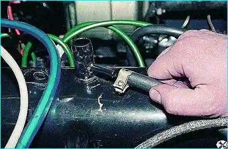
We disconnect the crankcase gas vent pipe.
We disconnect the vacuum regulator hose of the ignition distributor.
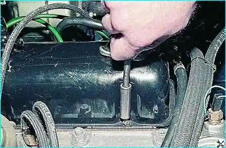
Using a 10 mm socket, we unscrew the six valve cover bolts.
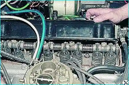
We remove the valve cover.
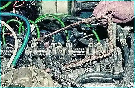
We extract the sealing gasket.
We set the piston of the 1st cylinder to TDC of the compression stroke.
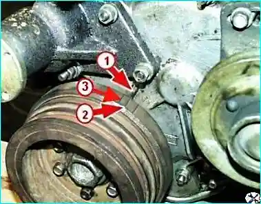
The third mark on the pulley must align with the lug on the timing sprocket cover.
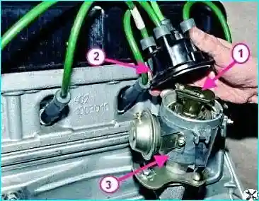
The distributor rotor must be in the 1st cylinder position.
At this, the inlet and exhaust valves will be closed and the valve rockers can swing freely.
Check the clearance between the rocker and the valve with a feeler gauge. With a normal clearance, the feeler gauge must move between the rocker and the valve end with slight effort.
The clearance value is given in the table.
Valve train clearance values
| Cylinder | Valve | Clearance value, mm |
|---|---|---|
| 1 | Inlet | 0.40 – 0.45 |
| Exhaust | 0.35 – 0.40 | |
| 2 | Inlet | 0.40 – 0.45 |
| Exhaust | 0.40 – 0.45 | |
| 3 | Inlet | 0.40 – 0.45 |
| Exhaust | 0.40 – 0.45 | |
| 4 | Inlet | 0.40 – 0.45 |
| Exhaust | 0.35 – 0.40 |
If the clearance value differs from that given in the table:
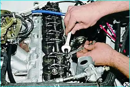
unscrew the lock nut with a 14 mm spanner, while holding the adjusting screw from turning with an 11 mm spanner.
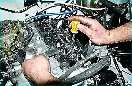
Then, turning the adjusting screw with a spanner (or a screwdriver inserted into the slot), adjust the clearance, checking it periodically with the feeler gauge.
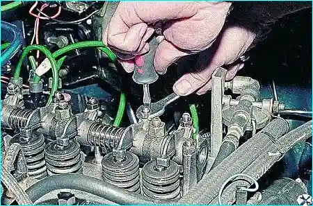
After that, holding the adjusting screw, tighten the lock nut.
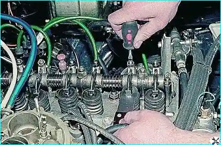
- Check the clearance once more with the feeler gauge. In the same way adjust the clearance on the other valve of the 1st cylinder.
- Turn the crankshaft half a revolution (180°) and adjust the clearances in the valve train of the 2nd cylinder.
- Turn the crankshaft another half revolution (180°) and adjust the clearances in the valve train of the 4th cylinder.
- Turn the crankshaft another half revolution (180°) and adjust the clearances in the valve train of the 3rd cylinder.
Tip
When turning the crankshaft, the correct position can be seen well by the distributor rotor.
On the end face of the distributor, the rotor positions can be marked with a marker or quick-drying paint.