The cars in the variant version are equipped with the anti-lock braking system (ABS) of the 8.1 series from Bosch
ABS is effective in emergency braking on roads with different surfaces (for example, asphalt - ice) and prevents the wheels from locking in less favorable traction conditions (on ice), providing the minimum stopping distance of the car for a given road surface while maintaining its stability and controllability.
This ABS has an electronic brake force regulator (EBD) function, which prevents the rear wheels from locking, causing the rear axle to skid when braking a partially loaded vehicle.
The ABS electrical part consists of 4 Bosch speed sensors located in the wheel assemblies of the vehicle, a Bosch hydraulic unit with a built-in electronic control unit in the engine compartment on the left, an ABS wiring harness, an ABS power harness, an ABS fault indicator and EBD malfunction indicator in the instrument cluster.
A GAZelle car with a 4 × 2 wheel arrangement is equipped with a Bosch hydraulic unit 0 265 231 980, speed sensors:
- 0 265 008 029 - front right;
- 0265 008 030 - front left;
- 0 265 008 033 - rear left;
- 0 265 008 034 - rear right.
Hydraulic unit 0 265 232 204 is installed on GAZelle cars with 4x4 wheel arrangement, speed sensors:
- 0 265 008 211 - front right / left;
- 0 265 008 033 - rear left;
- 0 265 008 034 - rear right,
- and, additionally, an acceleration sensor 0 265 005 146 is installed, located on the adapter bracket installed on the right side of the pedal bracket, as well as a wiring harness that connects the acceleration sensor to the ABS harness.
Each time the ignition is switched on, the ABS fault warning lamp and the EBD fault warning lamp turn on for about 3 seconds and then turn off. This indicates the health of the electrical components and circuits of the ABS, as well as the EBD system.
A short-term activation of the ABS or ABS and EBD malfunction indicator is allowed when the engine is started.
The ABS and EBD malfunction indicators also come on when the circuit from the instrument cluster to the electronic control unit is open.
A permanently on state of the ABS malfunction indicator (orange), or turning it on while driving, indicates an ABS malfunction. At the same time, the service brake system retains its functionality as without the ABS.
The permanently on state of the ABS malfunction indicator and the EBD malfunction indicator (red) or their activation while driving, indicates a malfunction of the ABS and EBD system.
Electrical - a schematic diagram of the ABS brakes of a car with a 4x2 wheel arrangement is shown in Figure 1
Electrical - a schematic diagram of the ABS brakes of a car with a 4x4 wheel arrangement is shown in Fig. 2
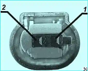
Contact numbers in the block to the ABS harness sensors
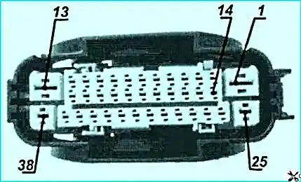
Contact numbers in the block to the hydraulic unit of the ABS harness
Diagnostics of the ABS brakes
ABS 8.1 (unlike ABS 5.3.) Does not have the ability to diagnose the system by light codes of the ABS malfunction indicator.
To carry out the ABS8.1 diagnostics, it is recommended to use the ASKAN-10 diagnostic tester-scanner (manufactured by NPP ELKAR LLC, Moscow), with the ABS GAZ diagnostic cable, with the ABS 8.1 diagnostic module installed for GAZ vehicles.
To diagnose the ABS, you must:
- - connect the ABS GAZ diagnostic cable to the tester's quick connector and to the battery;
- - at position "0" of the ignition switch key, connect the diagnostic connector to the vehicle's ABS diagnostic block.
The diagnostic connector is located on a bracket fixed under the attachment point of the windshield washer reservoir bracket;
- - after turning the ignition switch key to position "I" (ignition on), the tester display backlight will turn on and a splash screen will appear for a short time, and then the tester main menu.
To test the ABS of GAZ vehicles, it is necessary to run the ABS 8 diagnostic module from the GAZ package.
After starting the module, a short splash screen will appear on the display followed by the "MODE" menu.
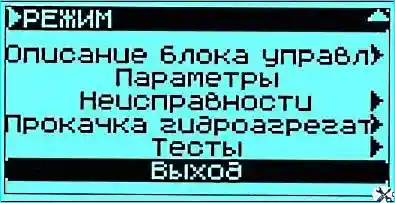
After the “MODE” menu appears, the green LED “LINK”, located on the front panel below the display, should turn on.
If the red "ERROR" LED, located on the front panel below the display, turns on, it is necessary to check the correct connection of the diagnostic cable and the integrity of the electrical circuit between the diagnostic block and the ABS hydraulic unit.
The "MODE" menu contains the following subsections:
- "Description of the control unit";
- "Parameters"; "Malfunctions";
- "Pumping a hydraulic unit";
- "Tests"; "Exit".
In the subsection "Description of the control unit" you can view the identification parameters of the hydraulic unit, change the coding option, view information about the diagnostic module.
In the subsection "Parameters" you can view the current parameters of the ABS.
In the subsection "Faults" you can view current and stored faults, erase fault codes, save faults in the tester's memory for printing.
In the subsection “Hydraulic unit bleeding”, the ABS hydraulic unit is pumped.
The subsection "Tests" is used to check the correctness of the connection of pipelines and the operability of the valves of the hydraulic unit, as well as the quality of the signals from the speed sensors.
In the "Exit" subsection, you exit to the previous menu.
An extended explanation of each subsection can be read on the tester display by pressing the "F3" key.
To get contextual help in each subsection, press the "F1" key.

The menu of the subsection "Description of the control unit" is shown in Fig. 6.
In the item "Identification" you can view the identification parameters of the hydraulic unit: the serial number of the hydraulic unit; manufacturer identifier; system name; control unit code; software code; Software version; Coding option - "Gazelle", "Gazelle 4x4".
In the item "Coding option" you can select the coding option corresponding to the model of the given car - "Gazelle", "Gazelle 4x4".
The display of a new coding option occurs only after exiting the ABS 8 diagnostic module and then entering this module.
Selecting a coding option that does not correspond to the model of the given vehicle is not allowed! Changes to the coding variant must only be carried out by a specialist!
The choice of the coding option is mandatory when installing a new hydraulic unit on the vehicle.
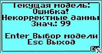
If there is no coding option (the hydraulic unit is in delivery state), when viewing the "Coding option" item, a message will appear on the display in accordance with Figure 7.
The absence of the selected coding option will lead to an error 4551 in the memory of the hydraulic unit control unit.
It is necessary to change the coding option in accordance with the model of the given car, then erase the existing codes of malfunctions using the "Malfunctions" menu.

To select a coding option, press the "Enter" key and select the desired option from the proposed list of car models (Fig. 8).
After selecting the current model, press the "Enter" key. Upon successful completion of the above operation, the display will show the inscription.
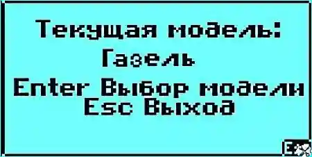
A conventional example of an inscription displayed on the display is shown in Fig. 9.
On cars with a 4x4 wheel arrangement, changing the coding option is not provided and is not available.
In this case, the message “Negative answer. This ECU implementation does not support changing the coding variant ".
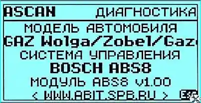
In the item "About the Program" - you can view information about the program module of this tester - scanner.
A conventional example of information displayed on the display is shown in Fig. 10.
In the subsection "Parameters" you can view the values of some parameters of the ABS system.
The parameter list is broken down into parameter pages.
The top line contains information about the title and number of the current page and the number of pages.
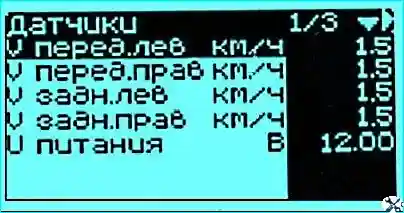
A conventional example of displaying parameters is shown in Fig. 11.
To switch to another parameter page, press the key with the ◄-- or --► symbol.
An extended explanation of each parameter can be read on the tester display by pressing the "F3" key.
To display the graph of the selected parameter, press the "F2" key.
In the dynamic view of the graph, the parameter values can be stopped at any point by pressing the "Enter" key.
In this case, pressing the keys with the symbol and makes it possible to view the graphs of the remaining parameters of this page, which stopped at the same point. Continuation of plotting is carried out by pressing the Enter key again.
Return to the initial parameter window by pressing the "Esc" key.
Saving the parameter page for subsequent printing is carried out by pressing the "Shift" keys and simultaneously "F2".
In the subsection "Faults" you can view current and stored faults, erase fault codes, save faults in the tester's memory for later printing.

The menu of the subsection "Malfunctions" is shown in Fig. 12.
The item "Current errors" allows you to view the codes of current (present in the ABS system at the moment) malfunctions and their description.

A conventional example of the display of the current error is shown in Fig. 13.
The top line of the displayed message contains the title of the window - "Error message", below it there is a line with two values.
The first value - "4040" indicates a digital code of malfunction, the second - "1/1" indicates the serial number of the malfunction / total number of malfunctions in the ABS system. The following is a description of the problem. The erasing of current faults, when viewing the current errors, occurs by pressing the "F3" key.
To save faults for subsequent printing, press the "Shift" keys and simultaneously "F2".
The item "Stored errors" allows you to view the codes of stored (stored in the memory of the hydraulic unit, not present in the ABS system at the moment) faults and their descriptions.
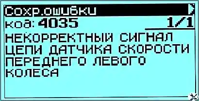
A conventional example of the display of the saved error is shown in Fig. 14.
After troubleshooting, it is necessary to erase the errors accumulated in the memory of the control unit of the hydraulic unit. The erasing of the stored faults, when viewing the stored errors, occurs by pressing the "F3" key.
To save faults for subsequent printing, press the "Shift" keys and simultaneously "F2".
Possible ABS malfunctions, their causes and remedies
Digital code of malfunction - Description of malfunction - Probable cause of occurrence - Remedies
4035 - Incorrect front left wheel speed sensor signal
Large, over 1.1 mm, gap between the sensor and the ABS gear rotor. Increased, more than 0.21 mm, runout of the ABS gear rotor relative to the axis of rotation. The geometry of the toothed rotor of the ABS is broken. Malfunction of ABS harness, malfunction of the speed sensor
- - Tighten the sensor mounting bolt to a torque of 7-10 N.m (0.7-1.0 kgf · m), while the ABS toothed rotor, when rotating, should not touch the sensor.
Adjust the tightening of the hub bearings. Replace the worn hub bearing or replace the hub assembly with bearing and rotor. Repair the malfunction of the ABS harness or replace the ABS harness. Replace speed sensor
Front Left Wheel Speed Sensor Circuit Malfunction - An open or short circuit in the sensor circuit to the negative or positive battery terminal. Open or short circuit
wires 1 and / or 2 in the ABS harness to the negative or positive battery terminal. Short circuit of wires 1 and 2 to each other.
The sensor is not connected to the ABS harness.
Faulty speed sensor
- Eliminate the malfunction of the ABS harness or replace the ABS harness. Connect the sensor to the ABS harness. Replace speed sensor
4040 - Incorrect front right wheel speed sensor signal
Large, over 1.1 mm, gap between the sensor and the ABS gear rotor. Increased, more than 0.21 mm, runout of the ABS gear rotor relative to the axis of rotation. The geometry of the toothed rotor of the ABS is broken. Malfunction of ABS harness, malfunction of the speed sensor
- Tighten the sensor mounting bolt with a torque of 7-10 N.m (0.7-1.0 kgf · m), while the ABS toothed rotor, when rotating, should not touch the sensor. Adjust the tightening
hub bearings. Replace the worn hub bearing or replace the hub assembly with bearing and rotor. Repair the malfunction of the ABS harness or replace the ABS harness. Replace speed sensor
Front Right Wheel Speed Sensor Circuit Malfunction - An open or short circuit in the sensor circuit to the negative or positive battery terminal. Open or short circuit
wires 5 and / or 6 in the ABS harness to the negative or positive battery terminal.
Short circuit of wires 5 and 6 to each other. The sensor is not connected to the ABS harness. Faulty speed sensor
Repair the malfunction of the ABS harness or replace the ABS harness.
Connect the sensor to the ABS harness.
Replace speed sensor
4045 - Incorrect rear left wheel speed sensor signal
Large, over 1.1 mm, gap between the sensor and the ABS gear rotor. Increased, more than 0.21 mm, runout of the ABS gear rotor relative to the axis of rotation.
The geometry of the toothed rotor of the ABS is violated (the absence of two or more teeth, nicks).
Malfunction of ABS harness, malfunction of the speed sensor
Tighten the sensor mounting bolt with a torque of 7-10 Nm (0.7-1.0 kgf · m), while the ABS toothed rotor, when rotating, should not touch the sensor.
Adjust the tightening of the hub bearings. Replace the worn hub bearing or replace the hub assembly with bearing and rotor.
Repair the malfunction of the ABS harness or replace the ABS harness.
Replace speed sensor
4050 - Incorrect rear right wheel speed sensor signal
Large, over 1.1 mm, gap between the sensor and the ABS gear rotor. Increased, more than 0.21 mm, runout of the ABS gear rotor relative to the axis of rotation.
The geometry of the toothed rotor of the ABS is broken.
Malfunction of ABS harness, malfunction of the speed sensor
- Tighten the sensor mounting bolt with a torque of 7-10 N.m (0.7-1.0 kgf · m), while the ABS toothed rotor, when rotating, should not touch the sensor.
Adjust the tightening of the hub bearings. Replace the worn hub bearing or replace the hub assembly with bearing and rotor.
Repair the malfunction of the ABS harness or replace the ABS harness. Replace speed sensor
Rear Right Wheel Speed Sensor Circuit Malfunction
Open or short circuit of the sensor circuit to the negative or positive terminal of the battery. Open or short of wire 7 and / or 8 in the ABS harness to the negative or positive battery terminal.
Short circuit of wires 7 and 8 to each other.
The sensor is not connected to the ABS harness. Faulty speed sensor
- Eliminate the malfunction of the ABS harness or replace the ABS harness.
Connect the speed sensor to the ABS harness. Replace speed sensor
4060 - Front left wheel reset valve circuit malfunction
Malfunction of the ABS hydraulic unit
- Replace the ABS hydraulic unit
4065 - Front left wheel cutoff valve circuit malfunction
Malfunction of the ABS hydraulic unit
- Replace the ABS hydraulic unit
4070 - Front right wheel reset valve circuit malfunction
Malfunction of the ABS hydraulic unit.
- Replace the ABS hydraulic unit
4075 - Front right wheel cutoff valve circuit malfunction
Malfunction of the ABS hydraulic unit
- - Replace the ABS hydraulic unit
4080 - Rear left wheel reset valve circuit malfunction
Malfunction of the ABS hydraulic unit
Replace the ABS hydraulic unit
4085 - Rear left wheel cutoff valve circuit malfunction
Malfunction of the ABS hydraulic unit
- - Replace the ABS hydraulic unit
4090 - Rear right wheel reset valve circuit malfunction
Malfunction of the ABS hydraulic unit
- - Replace the ABS hydraulic unit
4095 - Rear right wheel cutoff valve circuit malfunction
Malfunction of the ABS hydraulic unit
- - Replace the ABS hydraulic unit
4110 - Fault in the pump motor power supply circuit
Blown 40A fuse in fuse holder F41.
Lack of electrical contact of the wire 22 with the car body (the tip of the wire 22 is attached to the amplifier of the cab side member with the right).
Broken wire 14 and / or 16 and / or 17 in the ABS power harness. Broken wire 19 and / or 20 and / or 21 in the ABS harness. Malfunction of the ABS hydraulic unit
- - Replace the fuse in fuse holder F41. Provide electrical contact of wire 22 with the vehicle body.
Repair the ABS power harness or replace the ABS power harness. Repair the malfunction of the ABS harness or replace the ABS harness. Replace hydraulic unit
4121 - Valve power supply circuit malfunction
Blown 25A fuse in fuse holder F41.
Lack of electrical contact of the wire 22 with the car body (the tip of the wire 22 is attached to the amplifier of the cab side member with the right).
Broken wire 14 and / or 15 and / or 16 in the ABS power harness. Broken wire 18 and / or 20 and / or 21 in the ABS harness. Malfunction of the ABS hydraulic unit.
- - Replace the fuse in fuse holder F41.
Provide electrical contact of wire 15 with the vehicle body. Repair the ABS power harness or replace the ABS power harness. Repair the malfunction of the ABS harness or replace the ABS harness. Replace hydraulic unit
4161 - Broken wire from the hydraulic unit to the brake light switch
Malfunction of the harness brake switch circuit 99. Broken wire 11 in the ABS harness. Brake switch malfunction
- - Eliminate the faulty harness 99 or replace the harness 99. Eliminate the faulty ABS harness or replace the ABS harness. Replace brake switch
4245 - Incorrect wheel speed sensor signal
Breakage of any three groups of wires 1 and 2, 3 and 4, 5 and 6, 7 and 8 to the sensors in the ABS harness.
Broken wires 3 and 4, as well as 7 and 8 in the ABS harness.
Malfunction of any three ABS sensors or rear axle ABS sensors.
Wheel diameter discrepancy is more than 6%.
- - Eliminate the malfunction of the ABS harness or replace the ABS harness.
Replace ABS sensors. Install tires in accordance with the requirements for this vehicle, set the tire pressure in accordance with the requirements for this vehicle
4550 - Failure of the ECU of the hydraulic unit
Malfunction of the ABS hydraulic unit control unit
- - Replace the ABS hydraulic unit
Low voltage on-board network. The voltage between contacts 32 and 13, 38 of the hydraulic unit control unit is less than 9.3 V
- - Eliminate malfunctions associated with low voltage in the vehicle's on-board network. Repair harness 99 or replace harness 99.
Eliminate the malfunction of the ABS harness or replace the ABS harness
4800 - High voltage on-board network
The voltage between the contacts of the control unit of the hydraulic unit No. 1, 25, 32 and 13, 38 is more than 17.4 V
- - Eliminate malfunctions associated with increased supply voltage in the vehicle's on-board network
4551 - Encoding option error
No coding option (hydraulic unit as delivered)
- - Set the coding option, in accordance with the model of the given car
4287 * - Malfunction of the acceleration sensor - incorrect signal
The acceleration sensor is not attached. Acceleration sensor malfunction.
- - Check and, if necessary, tighten the bolts securing the acceleration sensor bracket and fastening the acceleration sensor to the bracket to a torque of 5.5-8.0 Nm (0.55-0.8 kgfm). Replace acceleration sensor
Acceleration sensor malfunction - line error
Broken wire 27 and / or 28 and / or 29 and / or 30 and / or 31 and / or 32 in the ABS harness and / or in the harness 154.
Shorting wire 28 and / or 31 to the negative or positive battery terminal.
The sensor is not connected to the harness 154. The ABS harness 154 is not connected to the ABS harness.
Sensor malfunction
- - Eliminate the faulty harness 154 or replace the ABS harness 154.
Repair the malfunction of the ABS harness or replace the ABS harness.
Connect the acceleration sensor to the harness 154. Connect the harness 154 to the ABS harness. Replace acceleration sensor
* - only for a car with a 4x4 wheel arrangement
Bleeding brakes with anti-lock braking system installed
Using the subsection “Bleeding the hydraulic unit”, air is removed and the internal circuits of the hydraulic unit are filled with brake fluid.
Bleeding the hydraulic unit is necessary only after installing a new hydraulic unit.
Hydraulic unit manufacturer, f. Bosch notes the need to use a pumping device that creates an overpressure of 2 bar (~ 2 kgf / cm²) in the brake fluid reservoir.
Before bleeding the hydraulic unit, bleed the brake system in the usual way.
The pumping of the hydraulic unit is carried out in 4 stages with the following mandatory sequence: pumping the left rear wheel; bleeding the left front wheel; bleeding the right front wheel; bleeding the right rear wheel.
In the process of pumping, it is necessary to press and release the brake pedal of the car at intervals of one pressing / release in about four seconds, while it is necessary to monitor the level of brake fluid in the master cylinder reservoir, avoiding a dry bottom.
Bleeding of the hydraulic unit is carried out only on a vehicle with an inoperative engine.
During pumping, the battery must be fully charged (the voltage between the contacts of the hydraulic unit 13, 38 and 1, 25, 32 must be in the range of 12-13.5 V).
During pumping of the hydraulic unit, it is necessary to put a tube on the pumping valve, placing the other end of the tube in a container with brake fluid, open the pumping valve of the corresponding wheel and press the brake pedal.

The menu of the subsection "Bleeding the hydraulic unit" is shown in Fig. 15.
To start pumping, select the pumping stages in the following sequence: pumping the left rear wheel; bleeding the left front wheel; bleeding the right front wheel; bleeding the right rear wheel.

After selecting the pumping stage, press the "Enter" key. The display will show a message as shown in Figure 16.
To start the pumping procedure, press the "F2" key.
Next, you need to open the bleed valve of the corresponding wheel and press the brake pedal at intervals of one press / release in about four seconds.

Upon successful completion of pumping, a message appears on the display in accordance with Figure 17.
Further, in accordance with the message displayed on the tester-scanner display, you should continue pumping in the usual way until air is removed from the hydraulic drive (see the section "Brakes", subsection "Filling (bleeding) the brake system").
At the end of the pumping of this wheel, press the "Esc" key.

The tester-scanner will display a message as shown in Figure 18.
In case of unsuccessful completion of the test, the message in accordance with Figure 17 is not displayed. In this case, repeat the bleeding procedure for the corresponding wheel. Further, if necessary, you should check the ABS malfunctions and eliminate them.
The rest of the pumping steps should be carried out in the same way.
If all the pumping stages have been successfully carried out and in the correct sequence (first the left rear wheel, then the left front wheel, then the right front and right rear), the display shows a message in accordance with Figure 19. In this case, in the “Parameters” section, the status of the “Fill” parameter changes from "stat" to OK.

The subsection "Tests" consists of two items: checking the correctness of the connection of pipelines and the operability of the valves of the hydraulic unit; check of speed sensors.
The test "Checking the correctness of connection of pipelines and the operability of the valves of the hydraulic unit" consists of 4 stages: checking the front left channel; checking the front right channel; check of the rear left channel; Checking the rear right channel.
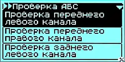
The menu for this test is shown in Figure 20.
This test is carried out on a biaxial or uniaxial treadmill test bench.
The speed of rotation of the rollers should be in the range of 2.5 to 10 km / h.
Before carrying out this test, it is necessary to install the tested axle of the car on the brake tester, turn it on and brake for the duration of the test (the pedal is released only after the test of the selected channel).
Checking one of the wheels of the checked axle is activated by pressing the "Enter" key.
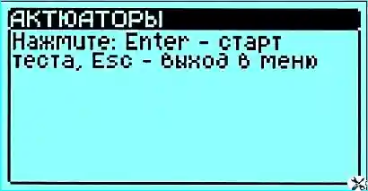
Then follow the instructions shown on the display of the tester in accordance with fig. 21.
In the process of performing this test, a temporary decrease in the braking force on the selected wheel should occur, which indicates that the pipelines are connected correctly and the valves are working.
Other channels are tested in the same way.
The speed sensor test allows you to check the quality of the speed sensor signals.
This test is carried out on a biaxial or uniaxial brake stand with running drums, at a constant speed of rotation of the stand rollers in the range from 2.5 to 10 km / h.
Before carrying out this test, it is necessary to install the tested axle of the car on the brake tester and turn it on.
Next, you should select a test and activate it by pressing the "F2" key. On the display, in the line "state", the current state of the test will be displayed.

The status of the "Execution" test is shown in Fig. 22.
At the end of the test, the display will show the minimum and maximum speed measured by the speed sensors of the tested wheels.
All measured speed values can be viewed using the ▼ and ▲ keys.
The difference between the maximum and minimum speed values obtained from the wheel speed sensor on the display of the scanner - tester should not exceed 10% of the rotation speed of the stand rollers.
The test of the speed sensors of the other axle, when using a uniaxial stand, is carried out in the same way.
Removal and installation of the anti-lock braking system (ABS) hydraulic unit
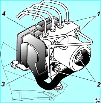
To remove the hydraulic unit, you must:
- - disconnect the block 3 (Fig. 1) of the ABS wiring harness from the plug connector of the electronic control unit of the hydraulic unit;
- - disconnect six pipelines from the hydraulic unit;
- - plug the holes in the hydraulic unit with plugs;
- - loosen the two nuts 2 securing the hydraulic unit to the bracket and remove the hydraulic unit.
During installation it is necessary:
- - install a rubber bushing 3 for the lower support of the hydraulic unit in the oval hole of the hydraulic unit bracket;
- - install hydraulic unit 1 in bracket 4;
- - carefully connect and tighten the six connecting nuts 1 (Fig. 2) fastening the pipelines to the hydraulic unit with a torque of 14-16 Nm (1.4-1.6 kgcm);
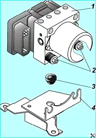
The nuts have different threads. Changing the connection points is not allowed.
- - tighten the two nuts 2 securing the hydraulic unit to the bracket with a torque of 8-9 Nm (0.8 - 0.9 kgcm);
- - use a special diagnostic program to check the software identification number of the ABS control unit, install the ABS wiring block in the plug connector of the electronic control unit of the hydraulic unit, add brake fluid to the reservoir and bleed the brake system and hydraulic unit.


