The steering of a car with a hydraulic booster and a rack-and-pinion steering mechanism.
The steering drive consists of two steering rods connected by ball joints to the levers of the steering knuckles.
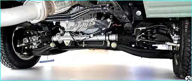
The steering mechanism is fixed to the front suspension crossmember.
The pressure of the working fluid in the hydraulic booster is maintained by a vane-type pump, which is driven by a belt from the engine crankshaft pulley.
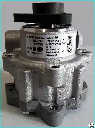
The fluid is supplied to the pump and under high pressure to the distribution valve mechanism mounted on the steering gear housing and connected to the steering column.
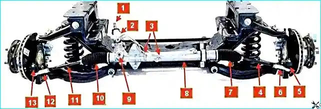
When the steering wheel is turned, the valve mechanism connects one of the cavities of the hydraulic cylinder, made in the steering gear housing, to the high-pressure line, and the second - to the fluid drain pipe into the tank.
The toothed rack, connected to the piston of the hydraulic cylinder, moves in the steering gear housing under the influence of the gear and the pressure difference in the hydraulic cylinder.
When moving, the rack transmits force to the steering knuckles through the steering rods, which leads to the rotation of the front wheels of the car.
If the amplifier fails, the ability to control the car is preserved, but the force on the steering wheel increases.

A trauma-safe steering column with a mechanism for adjusting its position by the angle of inclination is installed on the car.
The upper intermediate shaft is connected to the steering shaft by a cardan joint.
The lower end of the upper intermediate shaft is secured to the base of the cabin through a ball joint.
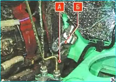
The fork "B" of the cardan joint of the lower intermediate shaft is attached to the lower end of the upper intermediate shaft by a clamp connection «А».
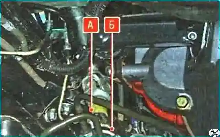
The lower intermediate shaft «А» is attached to the tailpiece «Б» of the steering gear pinion shaft by a similar clamp connection.
This design, when the frame is deformed during a frontal collision, prevents the steering column from moving further into the cabin, reducing the possibility of injury to the driver from hitting the steering wheel.
For additional driver protection, the steering shaft is made of two parts, united into a single whole by a splined telescopic connection.
The steering column contains: a switch for instruments and a starter (ignition switch) with an anti-theft device, blocking the steering wheel shaft from turning, as well as the controls for the headlights, turn signals, windshield washer and wiper, combined into a block of steering column switches.
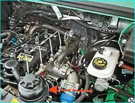
The power steering reservoir is mounted on a bracket in the front part of the engine compartment, on the upper cross member of the radiator frame and is connected by hoses to the power steering pump left control and the return line of the working fluid.
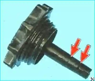
To control the fluid level in the tank cap, an indicator (dipstick) is mounted on which level marks are applied.
The steering rods are attached to the steering rack and to the steering knuckles of the front suspension with ball joints.
The steering rods are secured in the tips with lock nuts from turning.
The toe-in of the steered wheels is adjusted by rotating the steering rod in the tip.
Possible steering malfunctions and methods troubleshooting
Cause of malfunction (Remedy)
- 1. Increased free play of the steering wheel and knocks in the steering:
- - Loose tightening of the bolts and nuts of the steering gear - Tighten the bolts and nuts
- - Wear of the ball joints of the steering rods - Replace the outer ends or rod assemblies
- - Wear of the cardan joints of the intermediate shafts - Replace the intermediate shaft
- 2. Difficulty turning the steering wheel (insufficient power steering):
- - Slipping power steering pump drive belt - Replace belt
- - Damaged power steering pump drive belt - Replace belt
- - Insufficient working fluid level - Add fluid
- - Air entering the hydraulic system - Bleed air from the system
- - Kinked or damaged hoses - Eliminate kinking or replace hoses
- - Insufficient power steering pump pressure - Replace pump
- - Increased internal leaks in the pump - Replace pump
- - Fluid leaks from the steering gear - Replace defective parts
- 3. Unclear return of the steering wheel to the center position:
- - Difficulty turning the inner joints or joints of the tie rod ends - Replace the tie rod ends or tie rod assemblies
- - Deformation of the steering rack - Replace the steering gear
- - Damage to the pinion bearing - Replace the steering gear
- - Kinking or damage to the power steering hoses - Eliminate kink or replace the hoses
- - Damage to the pressure regulating valve - Replace the pressure regulating valve
- - Damage to the bearing of the pump rotor shaft - Replace the pump
- - Improper adjustment of the rack stop (overtightened) - Adjust the rack stop
- 4. Noise (knocking) in the steering:
- - Loose tightening of the steering gear mounting bolts and nuts - Tighten the bolts and nuts
- - Loose fastening of the steering rods or ball joints of the rod ends - Tighten the nuts
- - Wear of the ball joints - Replace worn parts
- - Violation of the rack stop adjustment (undertightened) - Adjust the rack stop
- 5. Increased noise from the power steering pump:
- - Insufficient level of working fluid - Restore the fluid level to normal
- - Air entering the hydraulic system - Remove air
- - Loose tightening of the pump mounting bolts - Tighten the bolts
The following are poured into the power steering system: oils for automatic transmissions Shell Spirax S2 ATF AX (Shell), ATF+4 (Mobil, Texaco, Castrol, Esso), (Mobil, Texaco, Castrol, Esso),
Checking the steering
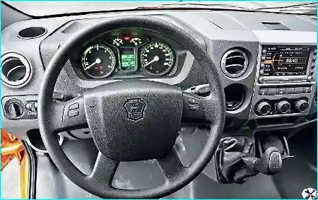
Check the location of the steering wheel spokes, which should be symmetrical relative to the vertical axis when the front wheels are straight.
Otherwise, determine the cause of the malfunction and eliminate it.
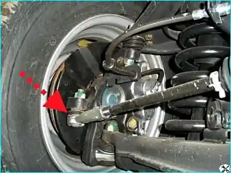
Check the condition of the protective covers of the steering rod ends
Replace any torn, cracked or elastic rubber covers, otherwise water, dust and dirt that gets into the units will quickly ruin them.
By sharply turning the steering wheel in both directions (this should be done by an assistant), check the steering gear fastening visually and audibly.
Moving the mechanism and knocking are not allowed.
If you find knocking and jamming that prevent the steering wheel from turning, disconnect the steering rods from the steering knuckle arms and repeat the check.
If the knocking and jamming do not stop, remove the steering gear from the car and repair it.
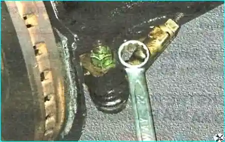
Check for play in the ball joints of the steering rod ends
Replace the ends whose joints have noticeable play.
Also check the reliability of tightening the nuts of the ball joints of the steering rod ends
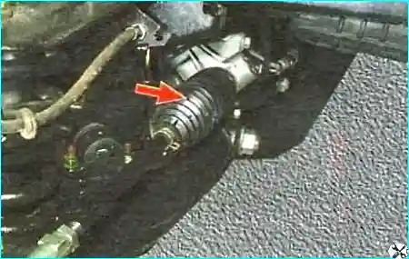
Checking the condition of the steering rod protective covers.
Replace damaged covers without fail
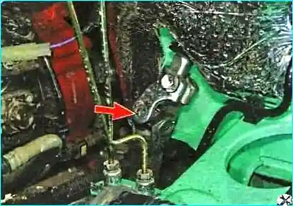
Checking the condition of the intermediate shaft cardan joints
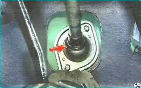
Checking the condition of the ball joint of the upper intermediate shaft
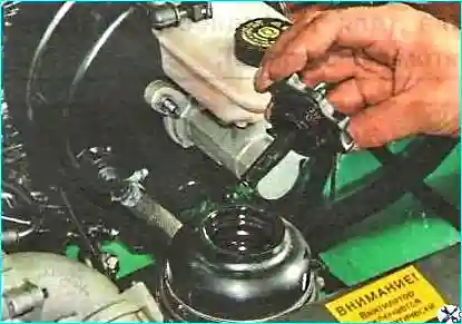
Checking the level and cleanliness of the working fluid in the tank
Check the condition of the hoses and pipes connecting the elements of the power steering system.
Eliminate any leaks found.
Checking the play of the steering wheel
You will need a ruler and chalk for marking.
With increased free play of the steering wheel, it is difficult to control the car, since it is late reacts to the driver's actions.
In addition, an increased stroke that cannot be eliminated by adjusting the steering gear indicates a malfunction of the steering (loosening of the steering gear, steering rods or wear of their parts).
Check the steering wheel play on a car installed on a flat, non-slip surface.
The play should not exceed 5˚.
For a steering wheel with an outer diameter of 360 mm, the play should not exceed 15-17 mm.
Set the front wheels to a position corresponding to straight-line movement.
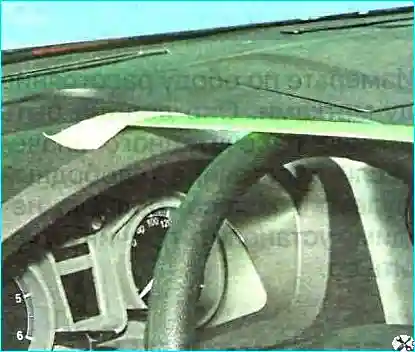
Install the ruler so that its end rests against the instrument panel, and the plane of the ruler touches the outer surface of the steering wheel rim.
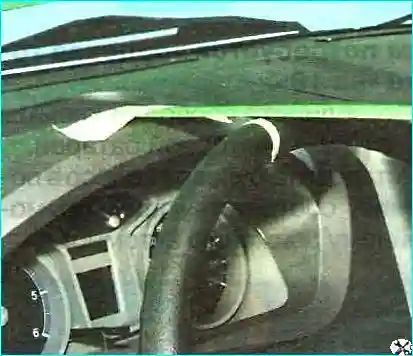
Without changing the position of the ruler, turn the steering wheel to the right until the front wheels begin to turn.
In this position, put a mark on the steering wheel rim.
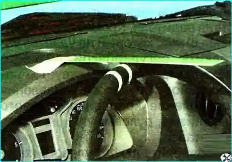
Without changing the position of the ruler, turn the steering wheel to the left until the front wheels begin to turn.
In this position, apply a second mark to the steering wheel rim.
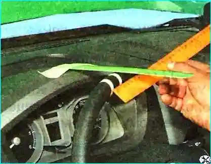
Measure the distance between the marks on the rim.
It should not be more than the calculated one values.
If the distance (steering wheel free play) is greater, it is necessary to determine the cause and eliminate it.


