The engine lubrication system is combined: the most loaded parts are lubricated under pressure, and the rest are lubricated either by directed spraying or spraying of oil flowing from the gaps between mating parts
The pressure in the lubrication system is generated by an oil pump installed in the front cover of the cylinder block and driven from the front end of the crankshaft.
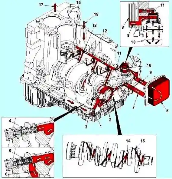
Scheme of the engine oil system: 1 - From the engine oil pan; 2 - Oil pump; 3 - Oil pressure regulator; 4 - Pressure control valve closed; 5 - The pressure control valve is open; 6 - Draining oil into the oil pan; 7 - Oil flow to the oil cooler; 8 - Oil cooler; 9 - Oil flow to the oil filter; 10 - Oil filter; 11 - Oil flow to the main oil line; 12 - Main oil line; 13 - Oil flow to the crankshaft; 14 - The main neck of the crankshaft; 15 - Connecting rod neck of the crankshaft; 16 - Piston cooling nozzle; 17- Oil flow to the valve train; 18 - Oil flow from the valve train
Oil enters the lubrication system through an intake pipe, through which it enters the gerotor-type oil pump.
After the pump, pressurized oil is supplied to a pressure control valve installed in the oil cooler cover.
Pressure control valve
The pressure control valve is designed to keep the lubricating oil pressure within 320 kPa.
If the oil pressure after the pump becomes more than 320 kPa, the valve opens, passing the oil into the discharge channel, through which it returns to the oil pan.
Taking into account technological tolerances for the manufacture of parts and oil lines, the lubricating oil pressure in various engines can vary up to 69 kPa.
Bypass valve
Further, the oil flow, passing through the oil cooler, enters the bypass valve, which opens if the pressure drop across the filter exceeds 345 kPa.
The opening pressure of the valve can vary within ±34 kPa.
Oil filter
After the oil cooler, the oil passes through a full-flow oil filter.
Oil that has passed the full-flow filter is sent to the main oil line of the cylinder block and turbocharger.
Turbocharger Lubrication
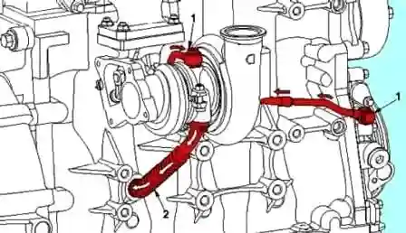
The turbocharger is the first block that receives filtered, cooled oil, passing under pressure through the pipeline from the front timing gear cover.
A drain pipe connected to the bottom of the turbocharger housing returns oil to the sump through a channel in the cylinder block.
Lubrication for parts under load
Main oil line
In addition, lubricating oil from the oil filter enters the main oil line through a channel at the front of the cylinder block, behind the front timing gear cover.
In addition, pressurized oil from the main oil line is supplied to lubricate the main bearings, valve train and drive accessories.
In addition, pressurized oil from the main oil line is supplied to other components and parts of the power train (rods, pistons and camshaft).
Oil from the main oil line is supplied to the main bearings, crankshaft, piston cooling nozzles and intermediate gear.
The crankshaft then supplies oil to the connecting rods.
The valve train is lubricated through separate channels drilled into the cylinder block.
Oil flows through holes and a slot in the cylinder head gasket.
Valve mechanism lubrication
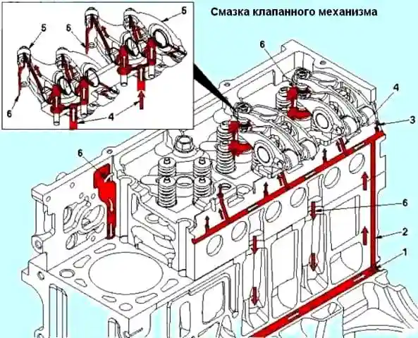
1 - Main oil line; 2 - Oil flow to the cylinder head; 3 - Oil flow to the camshaft; 4 - Oil flow to the valve mechanism; 5 - Rocker; 6 - Oil flow from the valve train
The channels drilled in the cylinder block continue in its head, approaching the holes in the rocker arms supports and camshaft journalsdriveshaft.
Through a channel in the support, oil flows to the rocker arm axis, its roller and the crosshead pad.
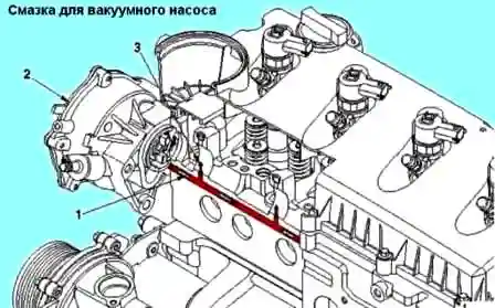
Through a channel in the cylinder block, oil is supplied to the vacuum pump drive, as well as to the camshaft chain tensioner.
Lubricating the rear timing gears
The rear timing gears and the camshaft chain drive are lubricated by a jet of oil coming from the hole in the cylinder head.
Oil is then drained back into the sump through the flywheel housing.
Severe-duty SAE15W40 oil recommended.
A low viscosity oil, such as 10W-30, can be used at low temperatures, which can provide the necessary oil supply at temperatures below -5˚.
But the constant use of low viscosity oils will shorten the life of the engine.
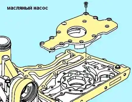
The engine uses a gerotor type oil pump located in the front timing gear cover, driven directly by the crankshaft.
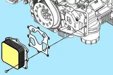
The oil is cooled using a full flow oil cooler, figure 6, which is located in the front timing gear cover.
The oil passes through the oil cooler fins where it is cooled by the engine coolant circulating behind the fins.
The oil is filtered using a full-flow oil filter, which is located on the intake manifold side at the front of the engine.
It is recommended to fill the filter with oil before installing it when replacing it to avoid delay in pressurization.
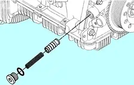
An oil pressure regulator is used to avoid high oil pressures.
The pressure regulator, figure 7, is located in the front timing gear cover, on the exhaust manifold side.
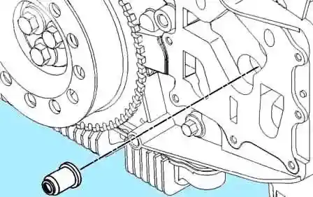
The lubrication bypass valve, figure 8, is mounted in the front timing gear cover, behind the oil cooler.
The bypass valve opens when the pressure drop across the oil filter becomes too high.
As a result, unfiltered oil continues to enter the engine lubrication system.
Engine oil pan
The oil pickup tube (arrow in fig. 9) is built into the oil pan.
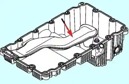
It is made of molded plastic and is friction welded to the oil pan.
The part of the tube immersed in oil is perforated to prevent large foreign particles from entering the lubrication system.
Crankcase pans on some engine models allow the installation of additional heaters to facilitate the operation of engines at low temperatures.
When diagnosing lubrication system failures, all obvious factors related to oil pressure should be checked.
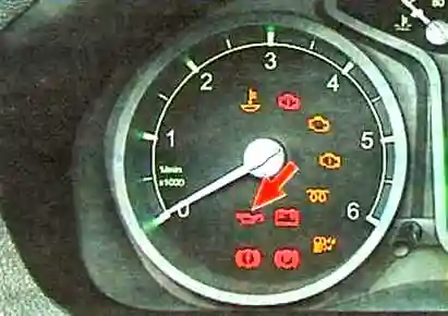
In the instrument cluster of the car there is a warning light for emergency oil pressure in the engine.
If the warning light comes on while the engine is running, loss of oil pressure and continues to burn at an increased speed, you must immediately stop the engine and find out the cause.
Checking the lubrication system
Open the hood and wait two or three minutes for the oil to glass into the crankcase and then check the oil level.
You need to look under the front of the car - if the engine oil sump is broken, if there is an oil leak.
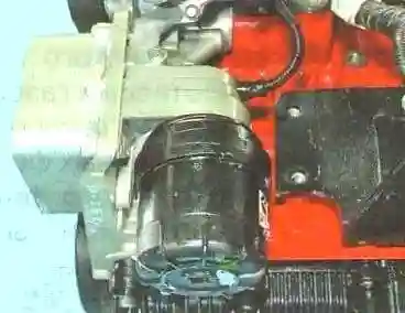
Pay attention to the oil filter.
Oil may leak from under the rubber gasket of the cover if it is damaged, or the filter itself if the filter is loose.
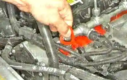
Remove the dipstick
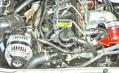
This is how the oil dipstick is located
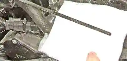
Wipe it with a cleaning cloth and set it in place

Re-remove the probe
The oil film level should be within the grooved area on the dipstick.
If the level is lower, then add oil to the norm.
Starting the engine.
If the signal light goes out at a normal level, you can continue driving.
If the lamp is still on, check the oil pressure sensor.
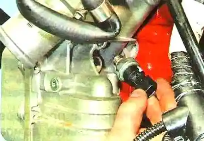
To do this, unscrew the oil pressure sensor, and install a mechanical pressure gauge in its place.
If the pressure at the minimum idle speed is more than 25 kPa (0.25 kgf / cm 2) and increases with increasing speed, the sensor or its electrical circuit is faulty.
A thin film of black oil on the dipstick indicates fuel.
Cloudy, colorless oil is a sign of the presence of coolant in the oil.
Possible causes of coolant in the oil:
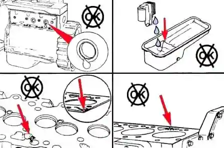
- - leakage through expansion plugs;
- - violation of the tightness of the oil cooler element;
- - damage to the cylinder head or gasket;
- - cracks in the cylinder block;
- - pores in cast parts.
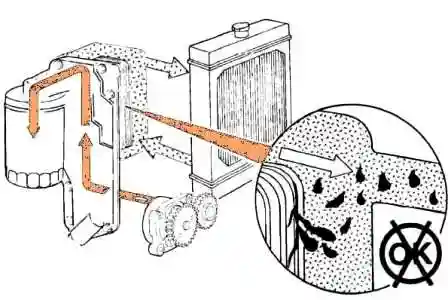
A leak in the oil cooler causes oil to mix with the coolant.
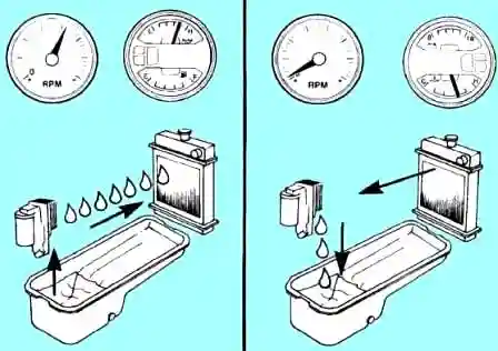
After turning off the engine, the presence of residual pressure in the cooling system can cause coolant to enter the oil.
To check the tightness of the lubrication system, you need to create a pressure of 140 kPa in it.
After that, remove the following parts and check for leaks:
- - rocker cover (leaks are a sign of cracks in the cylinder head);
- - drain plug of the engine crankcase (leaks indicate damage to the oil cooler, head gaskets, cracks in the head or cylinder block);
- - leaks through expansion plugs.
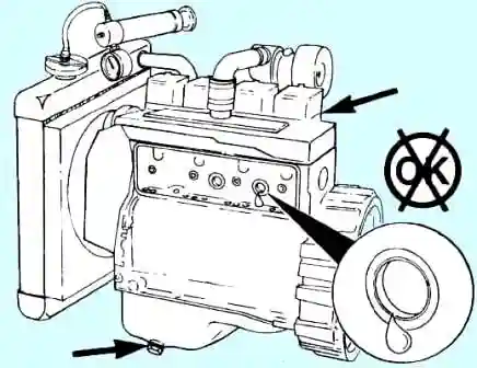
The presence of coolant in the oil can be caused by a damaged cylinder head gasket or cracks in the cylinder head or cylinder block.
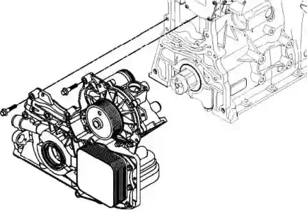
Coolant entering the oil can be caused by a damaged oil cooler gasket or front camshaft cover gasket.
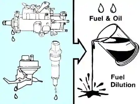
Fuel-thinned oil
There can only be five reasons why fuel dilutes oil:
- - Leakage through the shaft seal of the high pressure pump;
- - fuel leakage through piston rings;
- - booster pump;
- - a crack in the cylinder head at the junction of the fuel filter and the intake manifold;
- - leaks from injectors.
Applying logic when determining the source of fuel entering the oil:
- - Worn or damaged high pressure fuel pump shaft seal will cause fuel to enter the timing gear housing and then into the engine sump.
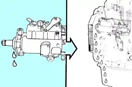
The seal design provides a tighter seal as pressure increases in the pump casing.
Pressure pushes edge 1 against the shaft more.
Worn seal will cause it to leak when starting and stopping the engine when case pressure is low.
This malfunction is difficult to determine by pressure testing the pump.
Incomplete combustion in the cylinders can cause unburned fuel to drip into the engine sump.
The reason for this may be a fuel leak through the injector or a decrease in compression due to poor performance of the piston rings.
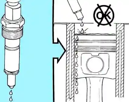
An increase in white smoke when starting the engine for the first time indicates a leak in the injector.
Fuel leaking through the injector also results in uneven engine operation and loss of power.
The nozzle needs to be removed, repaired or replaced.
Oil system malfunctions and solutions
- - Reason
Troubleshooting
Increased oil consumption:
- - Check the oil consumption rate
Compare the amount of oil added with the mileage of the car
- - External oil leaks
Check engine for external oil leaks, locate leaks, repair if necessary
- - crankcase ventilation system clogged
Check and clean the crankcase breather and vent pipe
- - Oil mismatch with technical requirements
Change oil and filter
- - Increased interval between oil drain operations
Make sure your oil change intervals are correct
- - Violation of the tightness of the oil cooler
Check for coolant leaks in the oil cooler
- - Oil level above normal
Check the oil level.
Check dipstick calibration and oil pan capacity. Add oil to the required level
- - The angle of inclination of the engine during operation is above normal
See Engine Specifications - Engine Tilt Requirements
- - Turbocharger seal leakage
Check the compressor and turbocharger seals
- - Incorrect fit of piston rings (after engine overhaul or piston installation)
Check crankcase pressure.
In case of increased crankcase pressure, check that the piston rings are seated correctly.
- - Excessive valve stem clearance or damaged valve stem seals
Check valve stems and seals.
- - Increased wear of the valve guides in the cylinder head
Check the valve guides for wear.
Replace the cylinder head if necessary
- - Damage or wear of the piston or piston rings
Check the tightness of the intake system.
Check pistons and piston rings for damage or wear.
- - Internal engine damage
To determine the location of possible damage, analyze the composition of the oil and check the filters.
Oil pollution:
- Determine what oil is contaminated with
Conduct an oil composition analysis to identify contaminants


