The cooling system is used to maintain the operating temperature of the engine
The heat generated in the engine is absorbed by the coolant passing through channels in the block and cylinder head.
This heat is then removed from the coolant by air as it passes through the radiator.
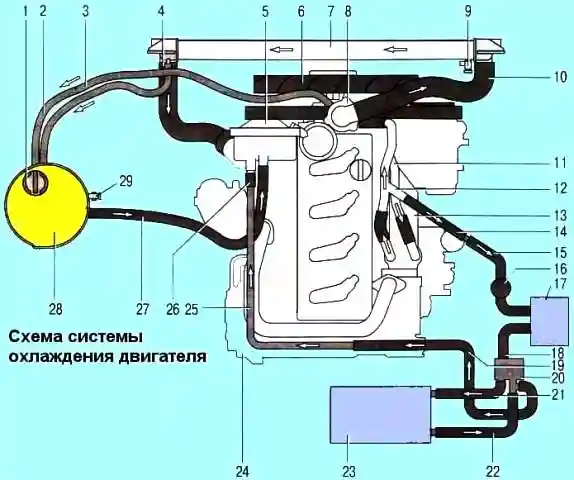
1 - expansion tank plug; 2, 3 - steam outlet hoses of the expansion tank; 4 - radiator outlet hose (to the coolant pump); 5 - water pump; 6 - fan with viscous coupling; 7 - radiator of the cooling system; 8 - thermostat; 9 - radiator drain valve; 10 - radiator inlet hose (from the thermostat); 11 - pipeline for supplying liquid to the heat exchanger of the exhaust gas recirculation system; 12 - pipeline for removing liquid from the heat exchanger of the exhaust gas recirculation system; 13 - heat exchanger of the exhaust gas recirculation system; 14, 15, 18, 19, 21, 22, 26 - hoses; 16 - electric pump of preheater; 17 - preheater; 20 - heater control valve; 23 - heater; 24 - engine; 25 - heater pipeline; 27- hose from the expansion tank to the water pump; 28 - expansion tank; 29 - coolant level sensor
The coolant enters the water pump located under the front timing gear cover and pressurizes the cooling system and enters the holes in the upper cavity of the cylinder block and the cylinder head gasket.
They are made around each cylinder and between cylinders.
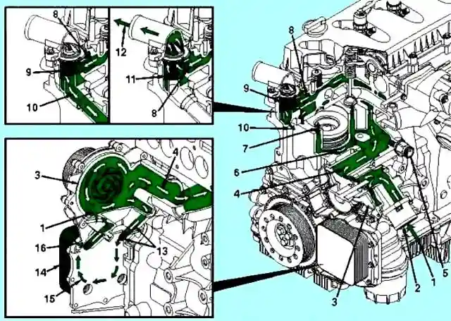
1 - Coolant flow from the radiator; 2 - Inlet pipe of the water pump; 3 - Pump of the cooling system; 4 - Coolant flow from the water pump to the cylinder block; 5 - Coolant heater; 6 - The flow of coolant around the cylinder liners; 7 - Coolant flow from the cylinder block to the cylinder head; 8 - Coolant flow from the cylinder head to the thermostat housing; 9 - The thermostat is closed, and the bypass channel is open; 10 - Coolant bypass to the water pump; 11 - The thermostat is open and the bypass is closed; 12 - Return of coolant to the radiator; 13 - The flow of coolant from the oil cooler to the main inlet line of the engine coolant; 14 - Oil cooler; 15 - The passage of the coolant through the oil cooler; 16 - Coolant flow from water pump to oil cooler
Coolant enters the cylinder head, flowing around the valve jumper and the injector installation site.
It then travels to the exhaust ports in the cylinder head through the OEM connections and into the thermostat housing.
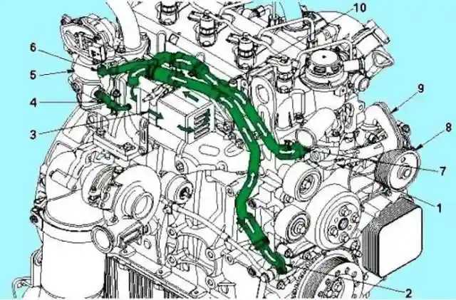
1 - Thermostat body; 2 - Coolant flow from the front cover module to the cooler of the exhaust gas recirculation system; 3 - The flow of coolant through the cooler of the exhaust gas recirculation system; 4 - To the valve of the exhaust gas recirculation system; 5 - Valve of the exhaust gas recirculation system; 6 - Line for draining the coolant from the valve of the exhaust gas recirculation system; 7 - Coolant drain line from the cooler of the exhaust gas recirculation system to the thermostat housing; 8 - Pump of the cooling system; 9 - Bypass pipe of the cooling system; 10 - Plug for air release from the cooler of the exhaust gas recirculation system
Until the engine warms up to the thermostat opening temperature, coolant is supplied through the bypass pipe to the water pump inlet.
Once the engine has warmed up to the thermostat opening temperature, the thermostat will open and coolant will flow through the radiator.
This will block the bypass channel through which it will get to the water pump.
The thermostat maintains the temperature in the range of 82 - 95˚ C.
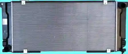
Radiator with a tubular-tape core and tanks made of polymeric material.
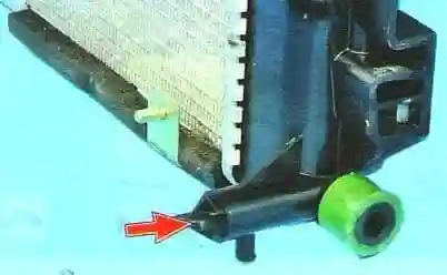
In the right tank there is a hole with a plug to drain the liquid from the cooling system.
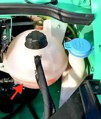
An expansion tank is installed to compensate for the amount of coolant depending on the temperature.
Liquid level marks are applied on the reservoir body.
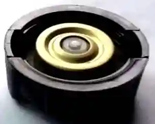
Reservoir cap with a release valve that maintains excess pressure in the system, allowing the coolant to start boiling up to 120˚
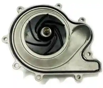
The water pump is mounted on the front cover of the cylinder block and is driven by the timing belt.
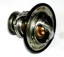
The thermostat is installed in a housing fixed to the cylinder block.
Closed to 82˚, opens at 95˚
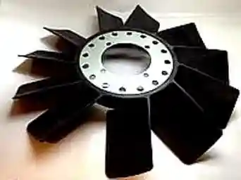
A fan with a plastic impeller is installed on the front cover of the viscous coupling and is attached to it with four bolts
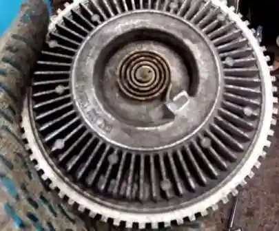
The fluid-friction fan clutch (viscous coupling) is mounted on a support and attached to it with a threaded bushing
The fluid-friction clutch allows you to change the fan speed depending on the temperature of the air flow passing through the radiator of the cooling system.
So, at low temperatures, the fan speed is minimal, as the temperature rises, its speed increases.
The clutch rotor is not rigidly connected to the housing on which the fan is installed, and the moment is transmitted due to internal friction of the working fluid.
The fan speed changes due to the flow of liquid volumes through the internal cavities of the coupling.
The flow of liquid occurs depending on the opening or closing of the internal channels of the coupling and is controlled by the movement of the reed valve.
Depending on the temperature, the valve position changes under the influence of a bimetallic spring.
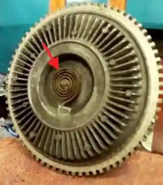
The bimetallic spring is installed outside the clutch in its front part.
The speed of the fan mounted on the viscous coupling housing increases as the air temperature rises and becomes equal to the speed of the engine crankshaft.
The reason for overheating of the engine, especially when driving in difficult road conditions or traffic jams, may be the failure of the fluid-friction clutch of the radiator fan.
To check the clutch with the engine off, check that the fan moves freely.
Check that the fan does not have strong axial and radial play.
Check that there are no traces of oil on the clutch. If there are traces of oil, the clutch must be replaced.
With the engine warm (hood closed), set the engine speed to approximately 3000 rpm.
The fan impeller will rotate at a low speed due to a small residual torque.
When the coolant temperature is 80-85˚ C, the clutch should start working.
The fan speed will greatly increase i (usually this is determined by increased noise).
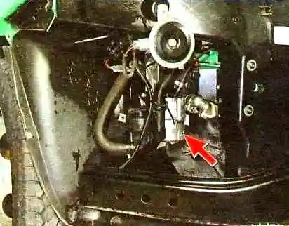
The preheater-preheater is installed in the right cavity of the front bumper (view in Figure 13 with the front bumper removed) on cars in the Comfort-2 configuration.
Due to the design features of the diesel engine, during its long idling operation (especially in the cold season), the temperature of the coolant gradually drops below normal, which, among other things, reduces the efficiency of the heater.
The preheater eliminates this drawback and at the same time performs the function of a preheater.
The unit runs on diesel fuel, which is supplied to it from the fuel tank by a special dosing pump.
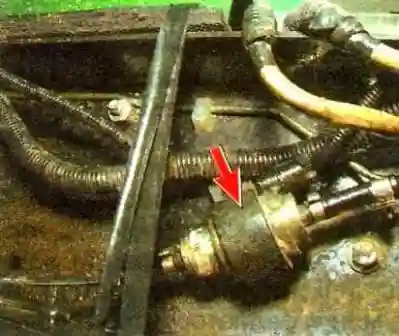
The dosing pump is installed on the inside of the vehicle frame and is connected to the fuel tank and the afterburner combustion chamber by special plastic fuel lines.
Checking the tightness of the cooling system connections
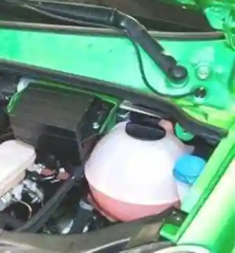
We look at the presence of coolant in the expansion tank
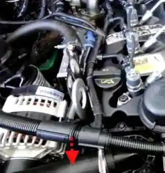
Checking the radiator inlet hose
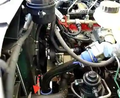
Checking the radiator outlet hose
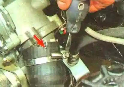
Inspecting the places where the hoses are attached to the water pump
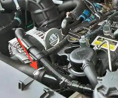
Inspecting the places where the hoses are attached to the thermostat
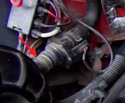
Inspecting the places where the hoses are attached to the heater tap
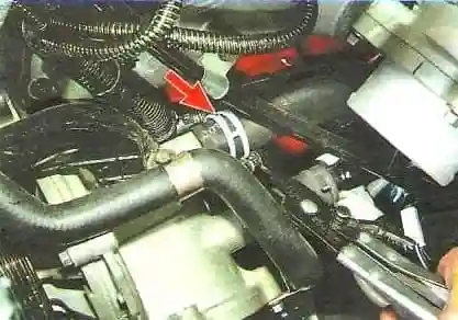
Checking the places where the hoses are attached to the pipes for draining fluid from the heater
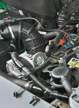
Liquid supply to the EGR heat exchanger
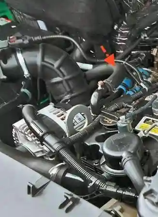
And the heater
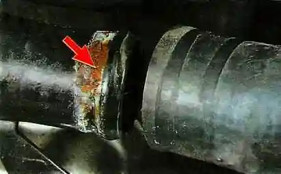
If you notice a leak, you need to remove the hose.
Leaking hoses are usually caused by corrosion of the sealing surface of the nozzles
You need to clean this place and apply sealant before installing the hose.
Possible malfunctions of the cooling system
- - Cause of failure
Troubleshooting
Coolant leaks:
- - External coolant leaks
check that there are no coolant leaks from hoses, drain cocks, water manifold, jumper tubes, expansion plugs and pipe plugs, fittings, coolant supply and return lines, cooling system ventilation of the exhaust gas recirculation system, turbocharger coolant supply and return lines, EGR valve coolant supply and return lines, EGR cooler and valve, radiator heat exchanger element, compressor and cylinder head gaskets, oil cooler, water pump seal, and OEM installed parts that are connected to the engine cooling system. If necessary, pressurize the cooling system.
- - The cap of the expansion tank is incorrectly selected or designed for low pressure
Check the expansion tank cap or replace it
- - Deformation, blockage or leakage of the cooling system hose
Check the hoses
- - Clogged, clogged or improperly routed coolant or air lines
Check the correct laying of the coolant supply lines, the presence of clogging in them.
- - Air enters the cooling system
Make sure there is no air or combustion products in the cooling system
Gradual or sudden overheating of the coolant:
- - Electronic DTCs active or a large number of passive DTCs
Read trouble codes and diagnose with the INSITE kit
- - Radiator cover or front apron closed
Open the insulation cover or front apron of the radiator
- - Damaged or clogged radiator fins
Check the heatsink fins
- - Coolant level below normal
Check the coolant level. Check for leaks
- - The concentration of antifreeze in the coolant is not correct
Check the concentration of antifreeze in the coolant.
Add antifreeze or water to bring the concentration back to normal.
- - Damaged or missing fan shroud or air recirculation baffles
Check the fan shroud and air recirculation deflectors.
- - The fan drive belt is damaged or its tension is loose
Check the fan belt. Replace the belt if necessary.
- - Faulty fan drive or fan control system
Check the drive and fan control system
- - Faulty coolant temperature gauge or sensor
Check that the temperature gauge and sensor are working properly. Repair or replace them if necessary.
- - Expansion tank cap valve not working properly
Check or replace expansion tank cap
- - The thermostat is incorrectly selected or defective
Check if the thermostat is correct and correct
- - The presence of dirt, scale or sediment in the cooling system
Clean the cooling system
- - Coolant contaminated with oil
Check for oil leakage in the cooling system, change the coolant.
- - Faulty water pump
Check the pressure in the cylinder block. Replace water pump if necessary
Coolant temperature below normal:
- - The thermostat is incorrectly selected or defective
Check the thermostat in the catalog, check its performance
- - Faulty fan drive or fan control system
Check the drive and fan control system
- - Engine idling too long
Do not leave the engine idling for a long time.
Coolant in oil:
- - Faulty oil cooler
Check oil cooler
- - Internal coolant leaks
Perform pressure testing of the cooling system and look for internal coolant leaks
- Leaky cylinder head gasket
Check the cylinder head gasket
- - Cracks or pores in the cylinder head
Compress the cylinder head
- - Cracks or pores in the cylinder block
Check the cylinder block


