


Replacing the timing chain Cummins ISF2.8 (GAZelle NEXT)
We replace the chain when it is stretched and remove it during engine repair.
To replace the chain, the engine must be removed from the GAZelle NEXT vehicle.
Tools and materials required
To carry out the work you will need: 5 and 6 mm hex keys, 10 and 15 mm sockets, and a tool to hold the phase sensor trigger wheel and prevent it turning. You will also need a torque wrench, a mallet or rubber hammer, and wire to secure the chain.
Materials and parts used:
- New timing drive chain. It is recommended to use an original part or a quality equivalent. The chain is replaced when it stretches, which shows up as running noise, valve timing shift and faults on the camshaft position sensors.
- New timing case cover gasket.
- New chain tensioner cover gasket (if necessary).
- Heat-resistant sealant for the mating surface of the flywheel housing to the cylinder block.
- New tensioner shoe and chain damper — in case of severe wear.
- Engine oil (for lubricating the parts during assembly).
- Rags, cleaner for removing remnants of the old sealant and contamination.
Important: the flywheel housing weighs about 23 kg, so it must be removed with an assistant. The flywheel housing securing bolts differ in diameter and length — their location must be remembered or marked before unscrewing.
Preparation and removal
We remove the engine.
We set the No. 1 cylinder piston to TDC on the compression stroke (article – Setting No. 1 cylinder to TDC).
We unscrew the five bolts securing the timing case cover.
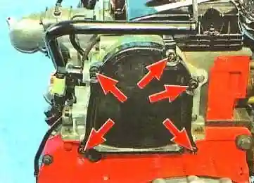
We remove the cover.
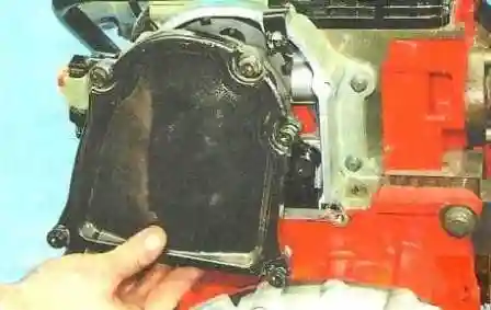
We remove the gasket. A new gasket must be fitted on reassembly.
We unscrew the two bolts securing the chain tensioner cover.
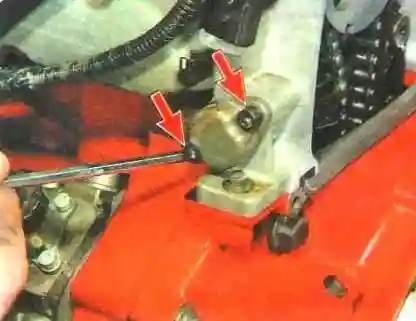
We remove the cover.
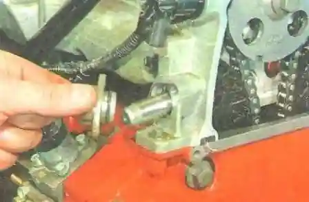
We extract the tensioner plunger.
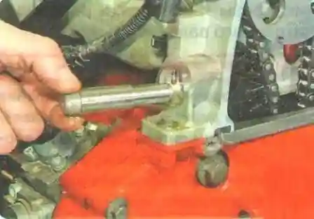
We secure the chain by tying it with wire.
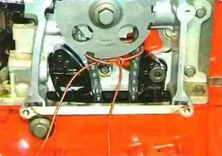
We slacken the bolt securing the trigger wheel and the camshaft sprocket while holding the shaft to prevent it turning.
We fully unscrew the bolt securing the phase sensor trigger wheel and the camshaft sprocket.
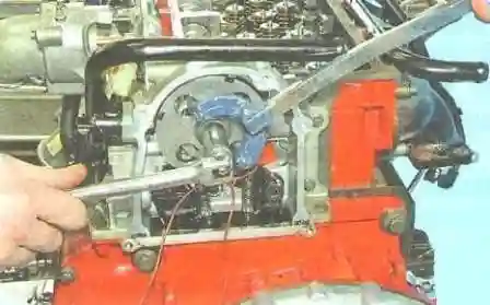
Caution: after unscrewing the bolt securing the phase sensor trigger wheel and the camshaft sprocket, neither the crankshaft nor the camshaft may be turned, so as not to disturb the valve timing.
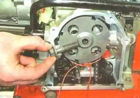
We remove the wheel.
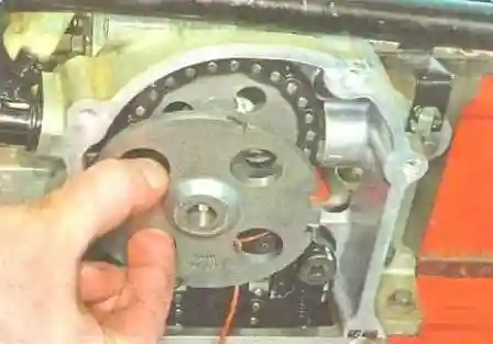
We remove the sprocket together with the chain from the camshaft nose.
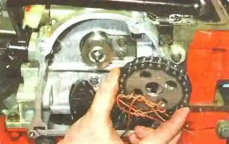
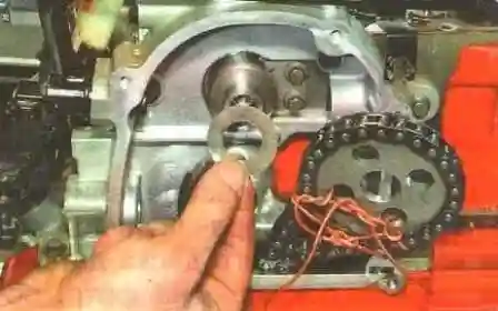
We extract the spacer washer so as not to lose it.
We secure the timing chain together with the sprocket on the engine.
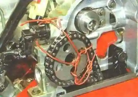
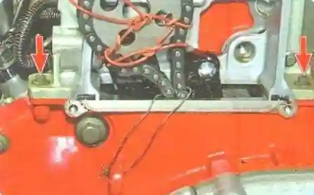
We unscrew the two bolts securing the timing case to the flywheel housing.
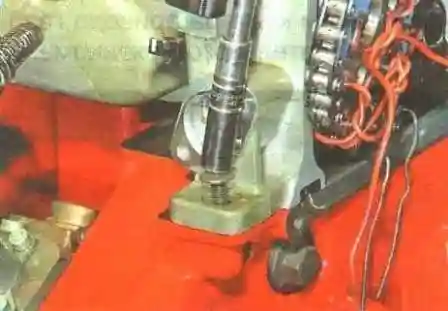
Location of the timing case securing bolts.
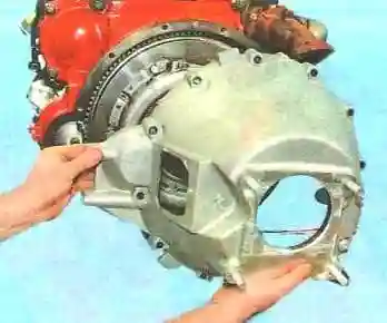
We remove the clutch housing.
We remove the flywheel (article – Removing and fitting the engine flywheel).
We unscrew the ten bolts securing the flywheel housing to the cylinder block.
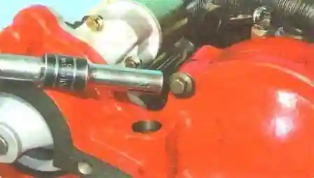
The flywheel housing securing bolts differ in diameter and length; their location must be remembered.
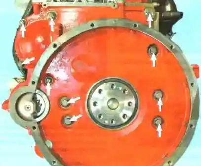
The flywheel housing weighs 23 kg, so it must be removed with an assistant.
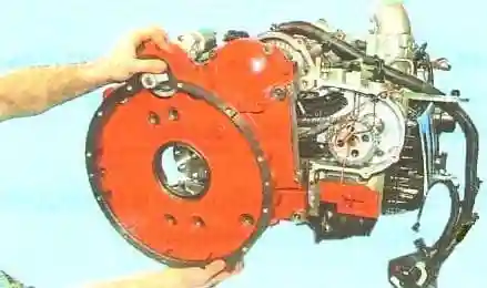
Using a mallet or rubber hammer, we free the housing and remove it together with the starter motor.
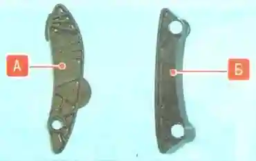
We unscrew the bolts securing the tensioner shoe “A” and the damper “B”.
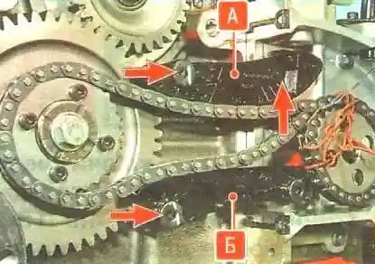
We extract the bolts and remove the shoe and damper.
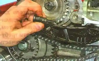
We inspect the tensioner shoe “A” and the damper “B”; in case of severe wear, we replace them.
We extract the camshaft sprocket from the chain.
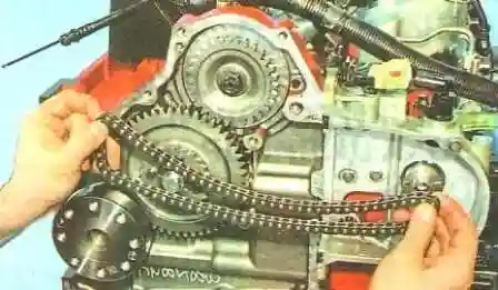
After taking the chain off the intermediate gear sprocket, we remove it from the engine.
Fitting the new chain and reassembly
We refit the chain and all the parts in the reverse order.
Before fitting the flywheel housing, make sure that the two dowel sleeves are still in place.
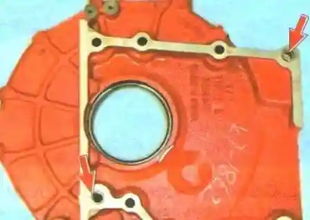
We apply heat-resistant sealant to the mating surface of the flywheel housing to the cylinder block.
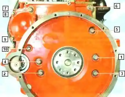
We tighten the bolts in the order shown in the figure. The M8 bolts are tightened to 24 N·m, and the M12 bolts to 85 N·m.
We check the valve timing.