

Replacing the cylinder head gasket Cummins ISF2.8 (GAZelle NEXT)
We replace the gasket because of coolant or engine oil leaks at the joints between the cylinder head and the cylinder block.
To replace the cylinder head gasket, the engine must be removed, since the timing drive chain has to be dismantled. Access to the valve train on an engine installed in the vehicle is impossible.
Tools and materials required
To carry out the work you will need: 8, 10, 15 and 16 mm sockets, a torque wrench, an extension bar, a ratchet handle, a set of screwdrivers, a set of flat feeler gauges, a metal straight edge, and a locking tool to hold the pulley.
Materials and parts used:
- New cylinder head gasket (MLS, multi-layer steel). It is recommended to use an original part or a quality equivalent (e.g. Victor Reinz, Goetze). The gasket with two notches (part no. 4943051) is approximately 1.15–1.20 mm thick and is intended for the standard piston protrusion.
- New cylinder head bolts (recommended, as the bolts are usually stretch bolts).
- Engine oil (for lubricating the bolt threads and seals).
- Timing case cover gasket (replace if necessary).
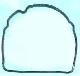
- Chain tensioner cover gasket (if necessary).
- Coolant and engine oil (for topping up after assembly).
- Rags, cleaner for removing remnants of the old gasket.
Important: when using a multi-layer steel (MLS) gasket, no sealant should be applied. The block and head surfaces must be perfectly clean and dry.
Preparation and removal
We prepare the vehicle for the work. We remove the engine.
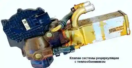
We remove the exhaust gas recirculation valve together with the cooler. We remove the turbocharger. We remove the cylinder head cover (see the article Replacing the cylinder head cover gasket).
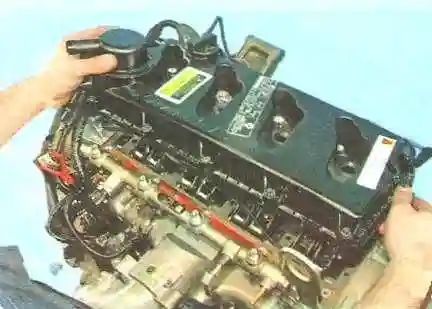
We set the No. 1 cylinder piston to TDC on the compression stroke (see the article Setting No. 1 cylinder to TDC).
We unscrew the five bolts securing the timing case cover.
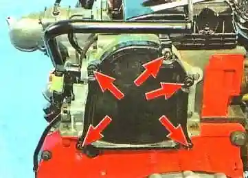
We remove the cover.
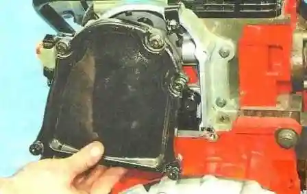
We remove the gasket. A new gasket must be fitted on reassembly.
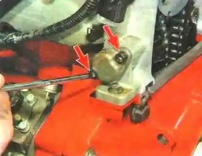
We unscrew the two bolts securing the chain tensioner cover.
We remove the cover.
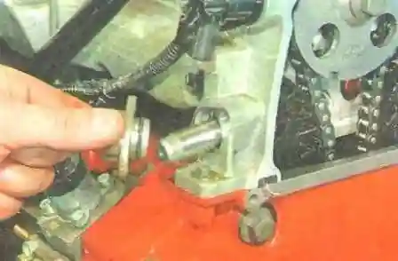
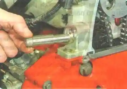
We extract the tensioner plunger.
We secure the chain by tying it with wire.
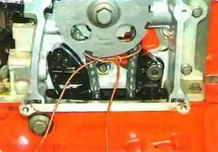
We slacken the bolt securing the trigger wheel and the camshaft sprocket while holding the shaft to prevent it turning.
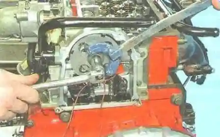
We fully unscrew the bolt securing the phase sensor trigger wheel and the camshaft sprocket.
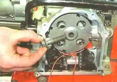
Caution: after unscrewing the bolt securing the phase sensor trigger wheel and the camshaft sprocket, neither the crankshaft nor the camshaft may be turned, so as not to disturb the valve timing.
We remove the wheel.
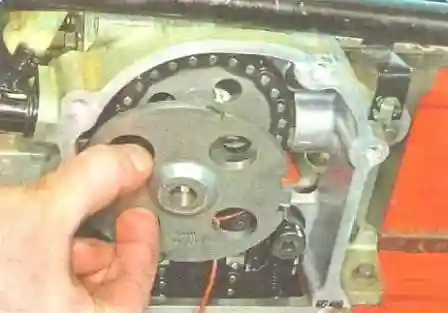
We remove the sprocket together with the chain from the camshaft nose.
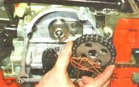
We extract the spacer washer so as not to lose it.
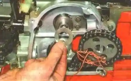
We secure the timing chain together with the sprocket on the engine.
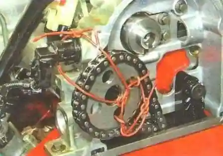
We remove the thermostat housing. We slacken the bolt securing the chain damper to the cylinder head.
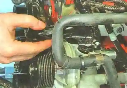
And unscrew the bolt.
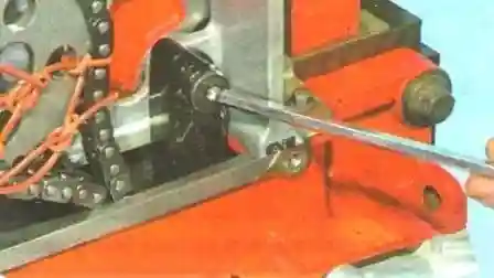
We unscrew the two bolts securing the timing case to the flywheel housing.
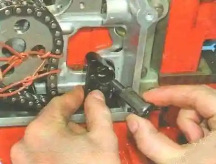
Location of the timing case securing bolts.
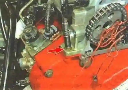
We unscrew the bolts securing all the rockers.
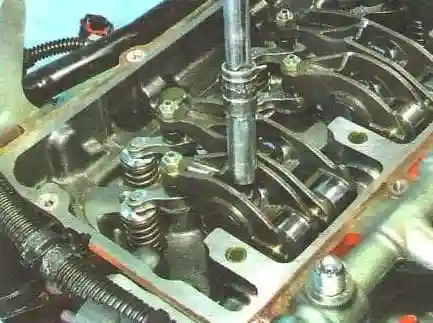
We extract the bolts.
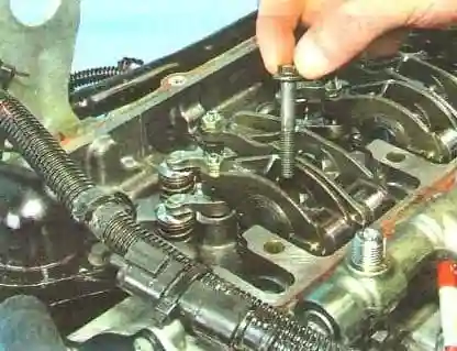
We remove the rockers.
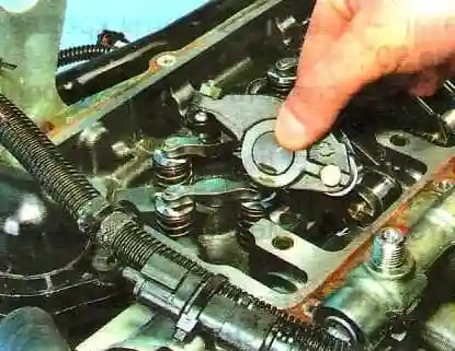
We extract the tappets.
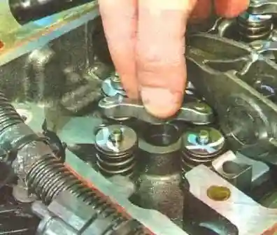
We withdraw the rocker shaft supports.
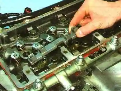
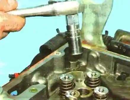
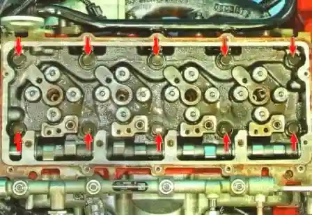
We unscrew the ten cylinder head securing bolts.
The location of the cylinder head securing bolts is shown in the figure below.
We untie the camshaft sprocket and chain from the cylinder head and remove the head together with the intake pipe, exhaust manifold and vacuum pump, keeping the timing chain taut.
Important: immediately after removing the cylinder head, secure the timing chain with wire in the taut position so that it does not slip off the crankshaft sprocket.
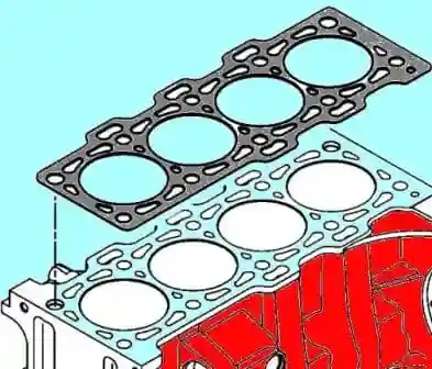
We remove the cylinder head gasket.
Inspection and preparation of surfaces
We inspect the mating surfaces of the head and cylinder block. We clean the mating surfaces of remnants of the old gasket.
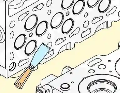
We check the cylinder head for distortion.
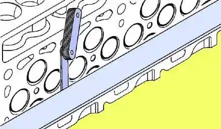
We place the straight edge on its edge on the head surface, first along the middle, then diagonally, and in every position of the straight edge we measure the gap between the head surface and the straight edge with a feeler gauge. If the gap is greater than 0.05 mm, the head is replaced.
Fitting the new gasket and reassembly
We take the new gasket out of its packaging immediately before fitting. We fit the new gasket to the cylinder block with the sealing bead facing upwards.
We refit the cylinder head in the reverse order, observing the following:
- Remove oil or coolant from the threaded holes for the cylinder head bolts that entered after the head was removed.
- Lubricate the bolts with engine oil.
- Screw in the cylinder head bolts and the two timing case bolts by hand, but do not tighten them.
Tightening the cylinder head bolts is carried out on a cold engine in the order shown in the figure below.
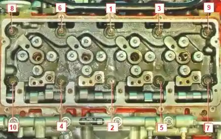
Tightening consists of three stages:
- First stage – tighten the bolts to 60 N·m;
- Second stage – turn the bolts a further 90°;
- Third stage – turn the bolts a further 90°.
We tighten the two timing case securing bolts to 4 N·m.
We refit all the parts in the reverse order. We adjust the valve clearances (see the article Adjusting the thermal valve clearances). We refit the engine to the vehicle.


