


If, when the clutch pedal is pressed, it reaches the stop without resistance and the clutch does not disengage, the clutch can only be disengaged by a sharp, rapid press of the pedal.
Consequently, the master cylinder piston seal has worn or been damaged.
Usually, repairing the master cylinder with seal replacement does not give the proper result, so it is better to replace the master cylinder.
Required materials and tools:
- New clutch release actuation master cylinder (and, if necessary, the slave cylinder).
- DOT-4 brake fluid.
- Syringe or bulb for extracting the fluid.
- Set of spanners, pliers.
- Graphite grease for the pedal bushes and pivot bolts.
- Container for used fluid, rags.
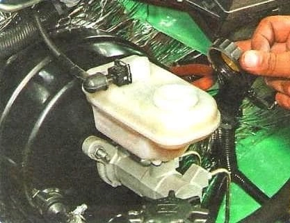
We open the master cylinder reservoir cap and extract the brake fluid with a syringe or bulb.
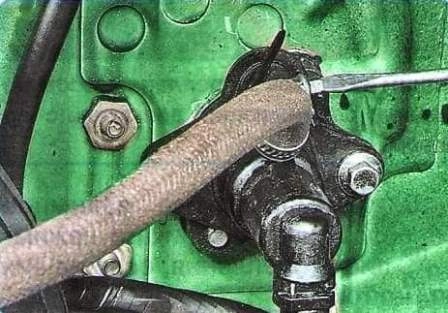
We loosen the hose clip, slide the clip along the hose and disconnect the hose from the master cylinder.
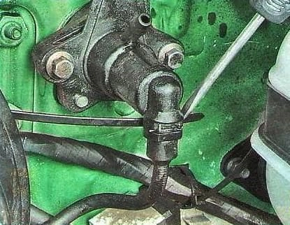
We push out the spring clip securing the hydraulic release actuation pipe to the master cylinder.
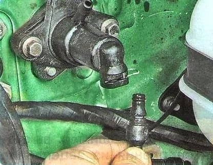
We disconnect the pipe.
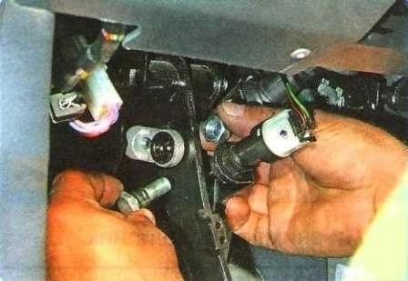
We disconnect the master cylinder pushrod from the clutch pedal.
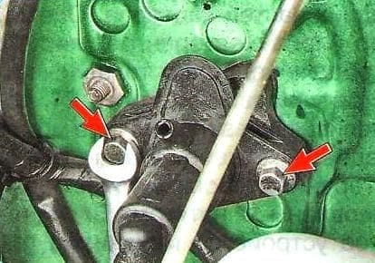
We unscrew the two bolts securing the master cylinder to the front panel.
We remove the master cylinder.
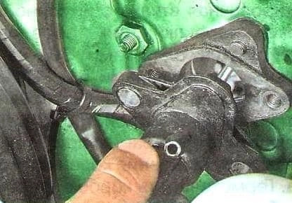
We install the clutch master cylinder in the reverse order.
We bleed the clutch hydraulic actuation.
If necessary, we adjust the clutch pedal position.
Removal and installation of the clutch release slave cylinder
We drain the fluid from the hydraulic release actuation.
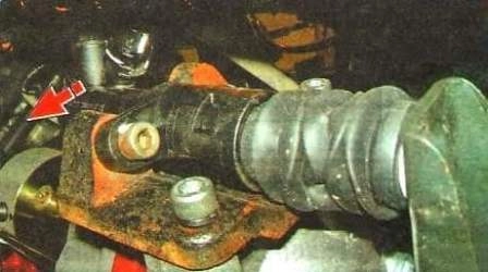
We push out the spring clip of the pipe end fitting of the hydraulic release actuation and disconnect the pipe from the slave cylinder.
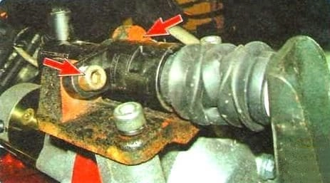
We unscrew the two bolts securing the slave cylinder to the bracket on the clutch housing and remove the slave cylinder.
We install the slave cylinder in the reverse order.
We fill the reservoir with brake fluid and bleed the clutch hydraulic actuation.
Removal, installation and adjustment of the clutch pedal position
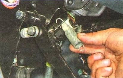
We disconnect the bent ends of the return spring from the pedal and the bracket and remove the spring.
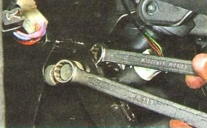
Holding the master cylinder pushrod bolt of the release actuation from turning, we unscrew its nut with a second spanner.
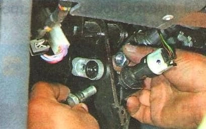
We extract the pivot bolt from the eye of the pushrod end fitting and the clutch pedal hole.
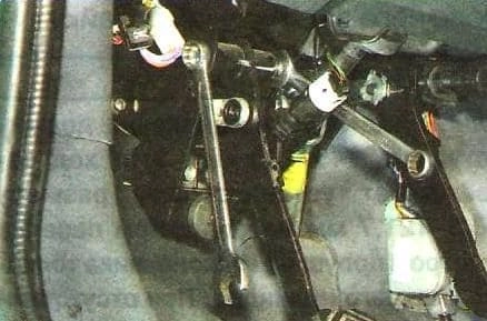
Holding the clutch pedal pivot bolt from turning, we unscrew its nut with a second spanner and extract the pivot bolt from the pedal eye and the bracket.
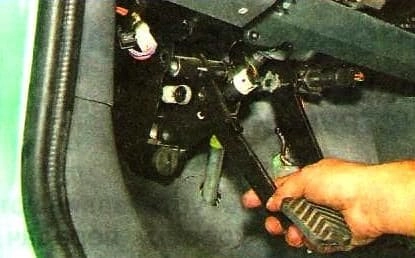
We remove the pedal.
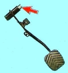
We extract the metal bush from the pedal eye and inspect it.
A plastic bush is fitted in the eye of the pushrod end fitting.
If the bush is heavily worn, we replace it.
We install the clutch pedal in the reverse order.
We coat the friction surfaces of the bushes and pivot bolts with a thin layer of graphite grease.
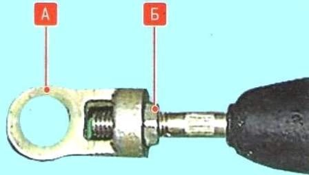
We adjust the pedal travel by changing the length of the master cylinder pushrod.
We loosen the locknut ‘Б' of the end fitting ‘А' of the pushrod and, turning the pushrod by hand or with pliers in the required direction, achieve the required result, after which we tighten the locknut.
The full clutch pedal travel must be 145—160 mm.
This travel corresponds to the installation dimension of 120.3—121.7 mm between the front panel and the centre of the eye of the master cylinder pushrod end fitting.
With no air in the hydraulic system, the installation dimension must ensure a full travel of the outer end of the clutch release fork equal to 21.5—23.5 mm.
The pedal free play is not adjustable.