


On the Cummins ISF2.8 power unit, the 5272666 three-phase AC generator from ZHEJIANG DEHONG is fitted.
The generator is a three-phase synchronous electrical machine with electromagnetic excitation.
The generator rotor is driven in rotation by the auxiliary drive belt.

Technical specification of the generator:
- rated voltage — 14 V;
- maximum current — 120 A;
- regulated voltage — 13.5–14.2 V.
Required materials and tools
- 10 mm and 13 mm spanners.
- Wheel chocks, jack, axle stand.
- Drift with a suitable-size mandrel.
- Torque wrench.
- Gloves and safety glasses.
Possible causes of generator faults
Cause of fault — Remedy
With the engine running, the display shows a voltage below 13.25 V and the battery discharges:
- breakage or slipping of the drive belt — adjust or replace the belt;
- open circuit in the excitation winding supply circuit — restore the connection;
- voltage regulator damaged — replace the regulator;
- generator faulty — replace the generator.
With the engine running, the display shows a voltage above 14.75 V and the battery overcharges (boils):
- voltage regulator damaged — replace the regulator.
Increased generator noise:
- generator pulley nut loose — tighten the nut;
- generator bearings damaged — replace the bearings;
- inter-turn short circuit or short to earth of the stator winding (generator whine) — replace the generator.
Removal of the generator
To remove the generator, 10 mm and 13 mm spanners are required.
We disconnect the negative battery terminal.
To work more conveniently, we remove the air filter.
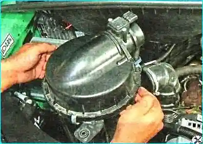
We remove the air intake hose.
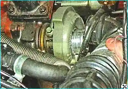
We remove the auxiliary drive belt (article — Replacing the auxiliary drive belt).
We unscrew the nut securing the excitation winding supply wire.

We remove the wire terminal from terminal ‘L' of the voltage regulator.

We unscrew the nut securing the power cable.

We remove the wire terminal from terminal ‘B+' of the generator.

We unscrew the left-hand short bolt.

We unscrew the right-hand long generator securing bolt.

We remove the generator from its mounting bracket.

We install the generator in the reverse order.
Before installing the generator, we push the threaded bush in the rear generator foot out by a few millimetres.
The bush is fitted with interference in the foot hole, so we use a drift with a suitable-size mandrel.

We tighten the generator securing bolts to a torque of 46 N·m in the following sequence: left-hand short bolt, then right-hand long bolt.