The cardan gear consists of an intermediate cardan shaft, an intermediate support, a rear cardan shaft and three cardan joints.
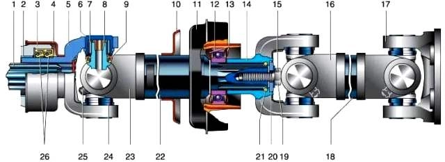
Cardan: 1 - secondary shaft of the gearbox; 2 - steel-babbit bushing; 3 - extension of the rear gearbox housing; 4 - sliding fork mud deflector; 5 - sliding fork; 6 - bearing housing; 7 - needles; 8 - cross; 9 - cuff; 10 - mud deflector; 11 - intermediate support; 12 - intermediate support bearing; 13 - protective rings; 14 - slotted fork; 15 - lock washer; 16 - fork of the rear propeller shaft; 17 - plug-flange; 18 - rear driveshaft; 19 - bolt; 20 - p-shaped plate; 21 - sealing ring; 22 - intermediate cardan shaft; 23 - fork of the intermediate cardan shaft; 24 - retaining ring; 25 - grease fitting; 26 - rear crankcase extension cuffs.
The intermediate cardan shaft is made of thin-walled steel pipe.
A shank with external splines is welded to the rear end of the intermediate shaft, and a fork is welded to the front end, to which a sliding front fork with an internal splined hole and a dirt deflector is attached through a cardan joint.
The front fork (tail) is inserted into the extension of the rear gearbox housing and engages with the splines of the secondary shaft.
During the operation of the rear suspension, the longitudinal displacement of the driveline occurs.
At the same time, the shank, moving along the splines of the secondary shaft of the gearbox, compensates for these shifts.
The spline connection is lubricated with oil poured into the gearbox housing.
The intermediate support is a rubber corrugated element; a closed ball bearing is vulcanized to it from the inside, and a bracket from the outside.
The rubber layer prevents the transmission of vibrations to the body and allows the driveline to move along the longitudinal axis of the vehicle.
The intermediate support bracket is bolted to the frame cross member.
The support bearing does not require maintenance throughout its entire service life.
The rear cardan shaft is made of a thin-walled pipe with forks welded to the ends.
A splined fork of the middle joint is attached to the front of the shaft through the cardan joint.
It is put on the rear spline of the intermediate shaft after the intermediate support.
It is fixed from displacements along the slots with a bolt with a lock washer.
A flange with a centering belt is attached to the other part of the rear propeller shaft through the hinge cross.
It is attached with four bolts to the final drive gear flange.
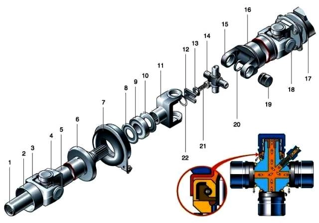
Details of the driveline: 1 - sliding fork shank; 2 - sliding fork mud deflector; 3 - sliding fork; 4 - fork of the intermediate cardan shaft; 5 - intermediate cardan shaft; 6 - mud deflector; 7 - intermediate support; 8.10 - protective rings; 9 - intermediate support bearing; 11 - slotted fork; 12 - U-shaped plate; 13 - lock washer; 14 - cross; 15 - fork of the rear propeller shaft; 16 - rear driveshaft; 17 - flange of the main gear drive gear; 18 - rear universal joint; 19 - needle bearing; 20 - retaining ring; 21 - bolt; 22 - sealing ring
The universal joint consists of forks and a cross with four closed needle bearings.
Each of them has 20 rollers (needles) with a diameter of 2 mm.
The needles are made with high precision, matched to this bearing assembly with the cross and are not interchangeable for different bearings.
Therefore, it is unacceptable to replace only the cross or bearings, the entire set is replaced as an assembly, even if at least one bearing is damaged.
A grease fitting is screwed into the cross.
From it, the oil pumped by a grease gun flows through the internal channels to the bearings.
The oil is retained inside the bearings by a rubber cuff with a spring.
When "syringing" the universal joint, the spring stretches and excess oil flows out.
Needle bearings are pressed into the coaxial holes of the forks and fixed in them with snap rings.
The cardan joints of all GAZ vehicles are traditionally lubricated with gear oil. This is not very convenient, you often have to inject the compound.
Fill the bearings with #158 grease, and you can forget about their existence for a long time.
When the gimbal is being repaired If you find that the spider has little wear, and it will still serve, turn it 180˚ around one of the axes of the spikes and assemble the hinge in this position.
The spikes will work on the non-worn side and the resource of the node will almost double.
Specifications of the driveline
The maximum allowable radial play of the cross bearings is 0.1 mm
The maximum allowable runout of the cardan shaft pipe is 0.6 mm
Runout of the pinion flange seat 0.15 mm
Gearbox output shaft runout 0.15 mm
Possible cardan failures
- Cause of malfunction
Remedy
Gimbal vibration during movement:
- Deformation of the cardan shaft pipe
Replace the propeller shaft tube or repair it with mandatory dynamic balancing
- Loosening the fastening of the rear driveshaft to the rear axle
Tighten threaded connections
- Separation of the balancing plate from the shaft tube
Replace the propeller shaft tube or repair it with mandatory dynamic balancing
- Increased play of the cross in the universal joint bearings
Replace universal joint bearings and crosses
- Increased runout of the seat belt of the drive gear flange of the rear axle reducer
Replace flange
- Increased runout of the sliding fork installed in the gearbox
Remove the cause of the output shaft runout.
Replace the gearbox extension due to worn steel-babbitt bushings
- Defective intermediate support bearing
Replace bearing
- Loose fastening of the intermediate support to the bracket or bracket to the bottom of the body
Tighten threaded connections
Knocks with a sharp change in the amount of torque transmitted by the driveline to the drive wheels:
- Increased backlash in splined joints, as well as wear on bearings and crosses of cardan forks
Replace defective parts and assemblies
Faults revealed during external examination:
- Oil leakage from the hinges due to damage to the cuffs
Replace cuffs
- Turning the cap with the cuff relative to the cup of the needle bearing (loss of a fixed fit and violation of the tightness of the hinge)
Replace the cross assembly with bearings, balance the driveline.
- Turning the cup of the needle bearing in the hole of the hinge fork
Replace worn parts, balance cardan gear
- When lubricating the hinge after 40,000 km of run, oil does not appear from under all cuffs
Remove the driveline, disassemble the hinge, clean the channels of the cross, close the bracelet springs into a ring and put on the cuffs.
After assembling the joint, dynamically balance the cardan shaft
Inspection, check and lubrication of the driveline
First of all, inspect the driveshafts and forks - cracks, dents or other deformations are unacceptable.
The polished surface of the sliding fork must be free of wear and tear.
The splines of the sliding fork, the output shaft of the gearbox, and the rear joint must not show signs of corrosion and wear.
Inspect the support - rubber peeling from the reinforcement, cracks and breaks are not allowed here.
The support bearing should rotate easily, without jamming or play.
On the removed driveline, you can assess the condition of the hinges without disassembling them.
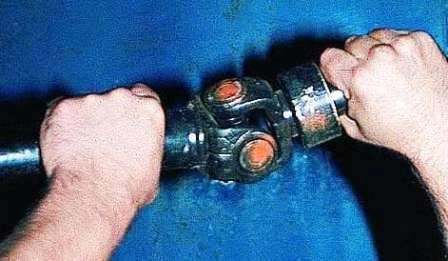
Shake each hinge in different planes. There should be no noticeable play along the axis of the spikes and jamming.
If necessary, you can measure the radial clearance in the bearings of the crosses with an indicator.
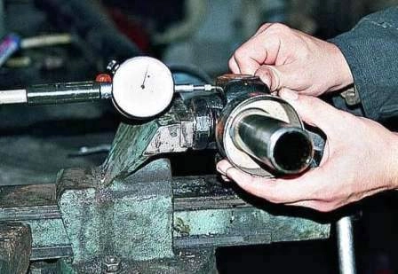
To do this, clamp one of the hinge forks in a vice on the bearings of the cross.
Pressing the indicator leg to the free eye of the other fork, swing it around the axis of the cardan shaft.
A play greater than 0.1 mm is not allowed. It indicates the wear of the hinge and the need to replace the bearings and the cross.
If the holes in the lugs themselves are worn out, the cardan shaft assembly must be replaced.
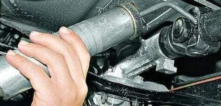
Steve from the dirt grease fitting, pump transmission oil into all joints with a syringe.
At the same time, its excess should come out from under the cuffs of all four bearings.
If the oil does not come out somewhere, then the hinge needs to be sorted out - the lubrication channel is clogged, the oiler valve is clogged, or a spring has come off one of the cuffs.
Removing the driveline
If the movement of the car was not accompanied by vibrations caused by the driveline, then during subsequent assembly, the pre-existing position relative to the gearbox and rear axle should be maintained.
To do this, turn on any gear in the box.
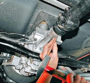
We mark with a chisel or file the position of the front fork (dirt deflector) of the cardan joint relative to the gearbox extension
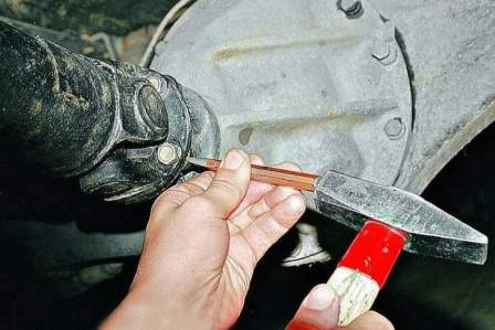
We mark with a chisel or file the position of the rear flange of the driveline relative to the flange of the rear axle.
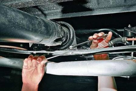
Using the “13” key, unscrew the nuts securing the intermediate support, holding the bolt with the “12” key.
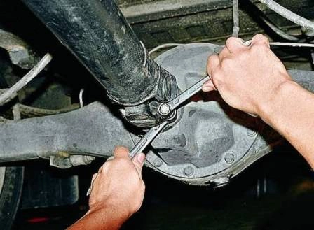
With the keys "14" and "17" we unscrew the bolts securing the driveline to the flange of the drive gear of the final drive.
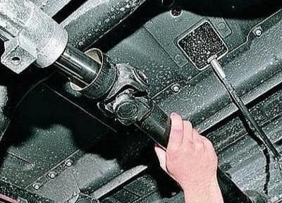
Sliding the driveline back, remove the sliding fork shank from the extension of the rear gearbox housing and remove the driveline.
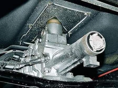
To prevent dust from entering the gearbox and leakage of oil from it, we plug the hole in the crankcase with a clean rag
Install the driveline in reverse order, matching the marks made.
We tighten the bolts of the driveline flange to the flange of the drive gear of the final drive to a torque of 30-36 Nm.
Nuts for the bolts of the intermediate support of the driveline to the frame cross member 12-18 Nm.
Disassembling the driveline and replacing the crosspieces
Since the driveline is balanced at the factory, each time it is disassembled and reassembled, it is necessary to maintain the original relative position of the shafts.
Otherwise, a noticeable vibration may occur when the vehicle is moving.
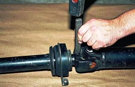
In order for the splines of the shank of the intermediate shaft and the splined fork to return to their previous position during assembly, we make marks with paint or a chisel on the pipe of the intermediate shaft
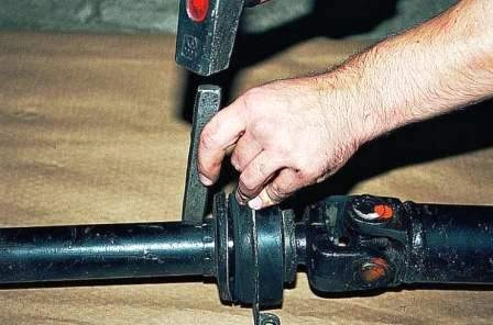
Make marks with paint or a chisel on the slotted fork of the middle hinge
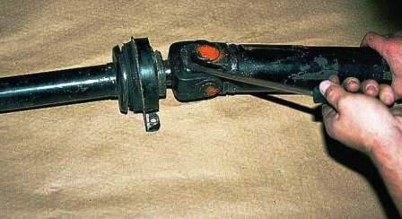
Use a screwdriver to bend the protrusion of the lock washer located inside the slotted fork
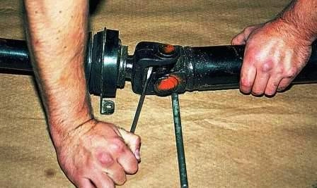
Having inserted a wrench or screwdriver into the fork, hold the hinge and unscrew the bolt three turns
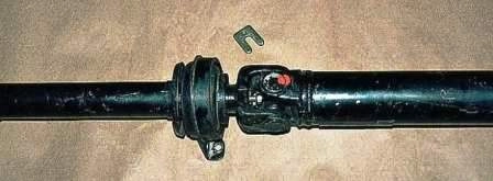
We take out the U-shaped plate with pliers
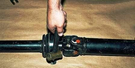
Using a copper hammer or through a spacer, we knock the fork off the splines of the intermediate shaft

Unscrew the bolt with the lock washer
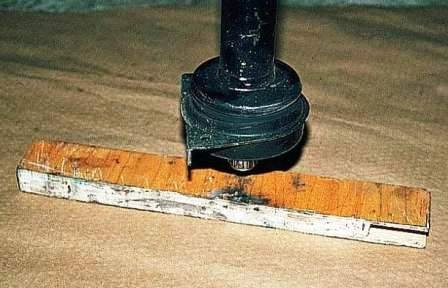
By hitting the splined shank of the intermediate shaft on the wooden lining, we knock down the intermediate support
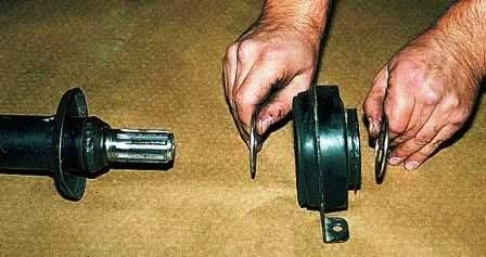
Remove the protective rings from the intermediate support
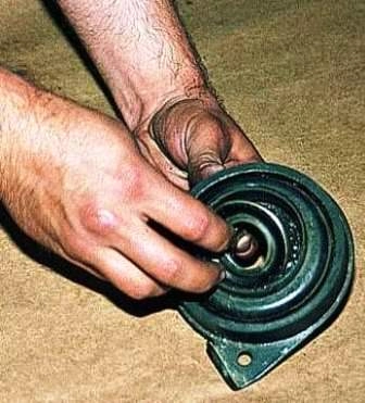
Before assembling the driveline, put Litol-24 grease into the grooves of the protective ring on the side facing the driveshaft and insert the ring.
We cover the splines of the intermediate shaft with CV joint-4 grease.
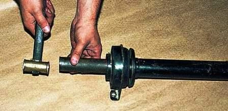
Using a mandrel made of a pipe (with a diameter approximately equal to the diameter of the inner ring of the bearing of the intermediate support), we press the support onto the splines of the intermediate shaft until it stops.
We put grease on the other side of the bearing and put on the second protective ring.
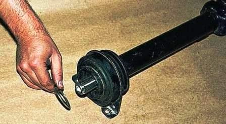
Install the O-ring into the undercut of the rear driveshaft yoke.
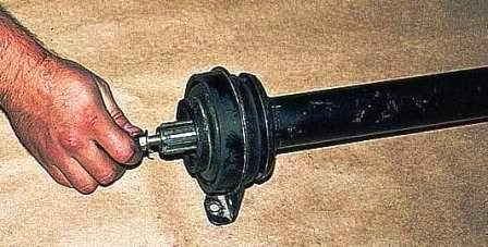
We wrap the bolt with a lock washer put on it into the end of the shaft, having previously lubricated the threaded hole with a few drops of sealant
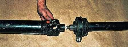
After applying a sealant belt 10 mm wide on the lead-in of the splines of the front shaft, we put on the fork, aligning the previously applied marks
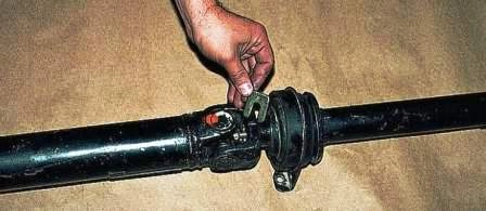
We insert the U - shaped plate under the lock washer so that the protrusion on the plate enters the cavity of the fork slot, and the antennae on the lock washer into the cutout of the plate.
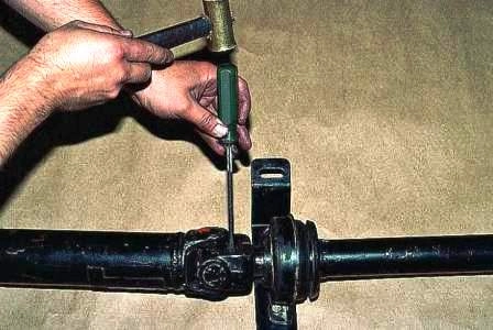
We wrap and tighten the bolt. We stop the bolt by bending the protrusion of the lock washer onto its edge.
The tightening torque of the slotted yoke bolt is 50-56 Nm.
Gimbal Disassembly
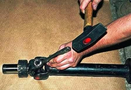
Having washed the hinge parts with kerosene, we mark their relative position.
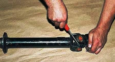
Prying off with a screwdriver, carefully remove the retaining rings of the bearings.
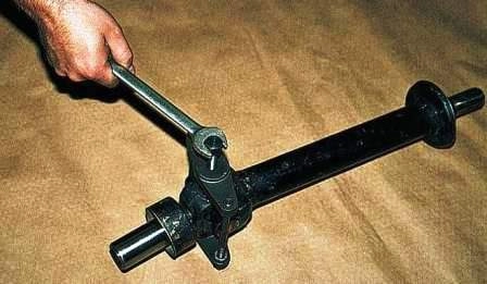
It is more convenient to disassemble the hinge with a special puller.
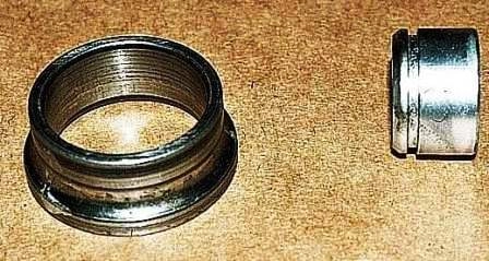
In its absence, we press out the bearing in a vice, for this we select a thrust ring and a mandrel from pipe sections or rings of old bearings.
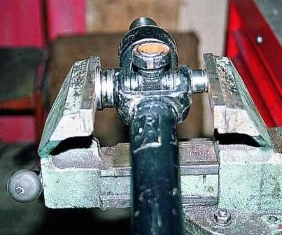
We clamp the hinge in a vice so that the mandrel is located on the side of the oiler and press out the bearings.
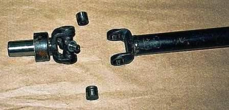
Having removed the bearings complete with cuffs from the cross, remove the plug.
Similarly, we press out the second pair of bearings (the cuffs should remain in the bearing housings) and take out the cross.
In case of installing a new hinge, we wash its parts from conservation grease.
We wash each bearing separately so as not to mix the needles. There should be chamfers at the ends of the cuffs, they can be made with a small needle file.
After drying the washed parts, we put the cuffs on the spikes of the cross so that the springs are facing the dirt deflectors.
Pour a little oil into the cups of the bearings and put them on the cross.
Now we remove three of them together with the cuffs, and leave the fourth (from the side of the oiler).
Further assembly of the hinge does not differ from the assembly of the hinge with parts that were in use.
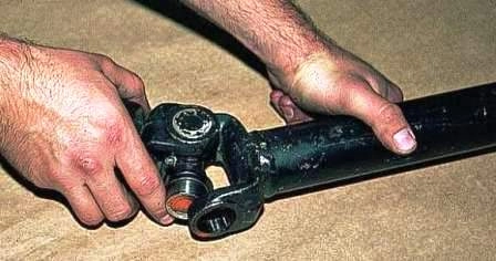
The free spike of the cross, opposite the oiler, is inserted into the eye of the fork, and then the opposite spike with a bearing and a retaining ring put on it - into the opposite eye
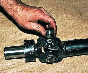
We put the bearing on the free spike by inserting it into the hole of the fork eye
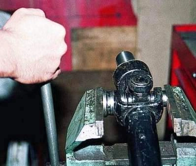
After making sure that both bearings are directed into the holes of the fork, we clamp the hinge in a vise, placing a thrust ring between the jaw of the vise and the eye of the fork
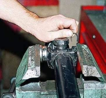
We press the bearing on the side of the oiler until the lock washer touches the fork eye.
We put the second locking ring on the opposite bearing.
We assemble both halves of the hinge in the same way, but do not forget to restore the relative position of the forks according to the marks made before disassembly.
When assembling the rest of the hinges, install the crosses so that the grease fittings of all the hinges are located in the same plane and on the same side of the hinge.
Device for disassembling cardan joints
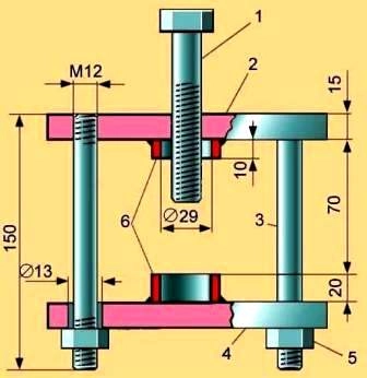
Device for disassembling cardan joints: 1 - M14x70 bolt; 2 - upper support plate; 3 - coupler (2 pieces); 4 - bottom support plate; 5 - nut M12 (2 pcs.); 6 - pipe sections with an inner diameter of 29 mm
Disassembly of any cardan joints will be easier and more convenient if you use the tool shown in the figure.
The distance between the base plates is selected depending on the dimensions of the hinge.


