The need to adjust the clearances in the valve drive is indicated by a distinct loud knock, audible when the engine is idling from the driver's seat with the hood closed
Increased clearances do not lead to emergency engine failures, but cause increased wear of the valve mechanism parts.
In addition, with increased clearances of the intake valves, the filling of the cylinders with a combustible mixture is worsened and, as a result, the engine power decreases.
With a complete absence of clearances in the exhaust valves, in addition to uneven operation and a decrease in engine power due to reduced compression in the cylinders, it is possible that the plates of these valves and their seats will burn out due to overheating, since the valve that does not fit tightly into the seat is poorly cooled.

The clearance should be measured on a cold engine, at a temperature of +20˚ C, between the tappet and the tip of the adjusting bolt with the valves fully closed.
The nominal clearance for intake valves is 0.25 mm, for exhaust valves 0.51 mm.
The two-arm tappet simultaneously acts on two intake or exhaust valves.
Prepare the car for work.
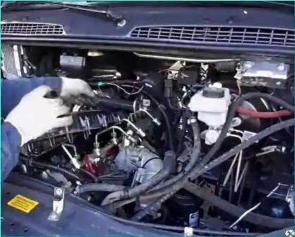
Remove the cylinder head cover.
Set the piston of the first cylinder to TDC of the compression stroke (article – Setting the TDC of the first cylinder).
In this position, all four valves of the first cylinder will be closed and the gaps between the tappet stops and the tips of the adjusting bolts will be maximum.
The cylinder count is carried out from the crankshaft pulley.
To set the piston of the 1st cylinder to the TDC position of the compression stroke, it is necessary to remove the timing disk of the phase sensor installed on the rear end of the camshaft (to gain access to the groove on the rear end of the camshaft), and this cannot be done on the engine installed on the car.
With an accuracy sufficient for adjusting the gaps in the valve mechanism, the camshaft can be set to the required position by monitoring its visually.
The camshaft must be turned so that the rocker rollers of the drive of all four valves of the cylinder being adjusted rest on the back of the camshaft cams, and the rocker arms can be moved by rocking within the gap.

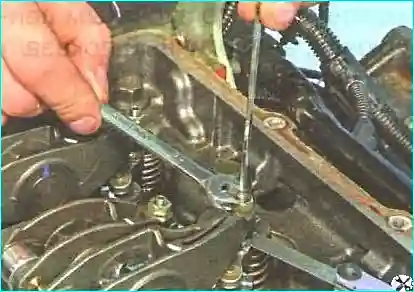
Loosen the tightening of the lock nut of the adjusting bolt of one of the rocker arms, holding the bolt from turning with a second key.
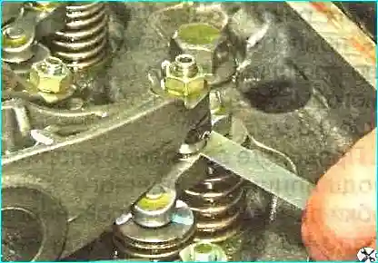
Insert the feeler gauge into the gap between the pusher stop and the tip of the adjusting bolt.
Holding the lock nut from turning, rotate the adjusting bolt clockwise until the feeler gauge in the gap can be moved with slight force.
Holding the adjusting bolt from turning, tighten the lock nut and check the gap.
Repeat the adjustment if necessary.
Adjust the gap for the second pair of valves in the same way.
Turn the crankshaft exactly half a turn.
With this position of the crankshaft, all four valves of the 3rd cylinder are completely closed and their rocker arms are released.
Adjust the gaps between the tappet stops and the tips of the adjusting bolts of the 3rd cylinder.
By subsequent turns of the crankshaft exactly half a turn, set the pistons of the 4th, and then the 2nd cylinder at TDC of the compression stroke and adjust the clearances for the remaining valves.
Install the cylinder head cover and all removed parts in the reverse order of removal.
If necessary, replace a heavily compressed cover gasket.
Ps. On the engine installed on the car, you can adjust the valves without removing the engine.
To do this, remove the cylinder head cover.

We insert a thin pin through the hole for the injector and, slowly turning the crankshaft, determine the top dead center in the cylinder.
The camshaft must be turned so that the rocker rollers of the drive of all four valves of the cylinder, the adjustment of which is carried out, rest on the occipital parts of the camshaft cams, and the rocker arms can be moved by rocking within the gap.
In this position, we check and adjust the gaps


