
The car has three independent braking systems: service, spare and parking.
The service brake system is hydraulic, dual-circuit (divided into front and rear circuits), with a vacuum booster, pressure regulator and a sensor for emergency drop in brake fluid level in the reservoir.
The spare system is formed by each circuit of the service system.
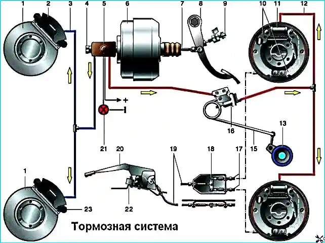
Brake system: 1 - brake disc; 2 - front wheel brake caliper; 3 - front circuit; 4 - brake master cylinder; 5 - reservoir with brake fluid level emergency drop sensor; 6 - vacuum booster; 7 - pusher; 8 - brake pedal; 9 - brake light switch; 10 - rear wheel brake shoes; 11 - rear wheel brake cylinder; 12 - rear circuit; 13 - axle shaft housing; 15 - load spring; 16 - pressure regulator; 17 - rear parking brake cables; 18 equalizer; 19 - front (central) cable; 20 - parking brake lever; 21 - brake fluid level emergency drop indicator; 22 - parking brake indicator switch; 23 - front wheel brake shoe
If one of the brake system circuits fails, the second circuit ensures the car's braking, although with less efficiency.
The parking system is mechanical, with a cable drive from the hand lever to the rear wheel brake shoes.
The front wheel brake mechanism is disc, with automatic adjustment of the gap between the shoes 7, Figure 2, and the ventilated disc 6, with a floating caliper.
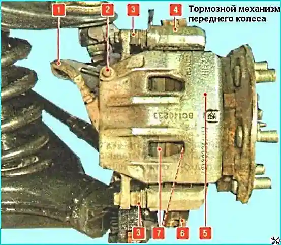
Front wheel brake mechanism: 1 - brake hose; 2 - air release valve; 3 - caliper guide pin (covered with a protective cover); 4 - shoe guide; 5 - brake mechanism caliper; 6 - brake disc; 7 - brake pads (the outer pad is not visible in the photo, as it is covered by the caliper)
The movable bracket is formed by the caliper 5 with a two-piston working cylinder.
The guide 4 of the pads is bolted to the steering knuckle.
The movable bracket is bolted to the guide pins 3 installed in the holes of the pad guide.
The guide pins are lubricated with consistent grease and protected by rubber boots.
Pistons with sealing rings are installed in the cavity of the working cylinders.
Due to the elasticity of these rings, an optimal gap is maintained between the pads and the ventilated disc.
When braking, the pistons, under the influence of fluid pressure, press the inner pad against the disc, as a result of the reaction force the caliper moves on the fingers and the outer pad is also pressed against the disc, while the pressing forces of the pads are the same.
When releasing the brakes, the pistons are moved away from the pad due to the elasticity of the sealing rings, a small gap is formed between the pads and the disc.
The tandem-type master brake cylinder of the hydraulic brake drive is installed in the engine compartment directly on the brake booster.
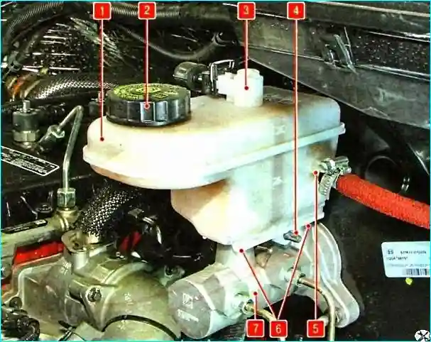
Master brake cylinder with a reservoir: 1 - main brake cylinder; 2 - reservoir cap; 3 - brake fluid level sensor; 4 - reservoir mounting screw; 5 - nipple for connecting the hose to the clutch master cylinder; 6 - connecting bushings (not visible in the photo, as they are covered by the reservoir); 7 - master brake cylinder
It consists of two separate chambers connected to independent hydraulic circuits.
The first chamber is connected to the rear brake mechanisms, the second - to the front ones.
A reservoir 1 is installed on the master cylinder through rubber connecting bushings 6 and secured to the cylinder with a screw 4, the internal cavity of which is divided by partitions into three compartments.
Each of the two main compartments supplies one of the chambers of the master brake cylinder, and the third compartment supplies the master cylinder of the clutch release hydraulic drive.
When the brake pedal is pressed, the pistons of the master brake cylinder begin to move, the working edges of the cuffs cover the compensation holes, the chambers and the reservoir are disconnected, and the displacement of brake fluid begins.
A sensor 3 of the brake fluid level is installed in the upper part of the reservoir liquids.
When the liquid level drops below the permissible level, the malfunction indicator lamp lights up in the instrument cluster brake system.
The flange for connection to the vacuum brake booster is sealed with a rubber ring.
The vacuum booster, installed between the pedal mechanism and the master brake cylinder, during braking, due to the vacuum created by the vacuum pump driven by the engine camshaft, through the rod and piston of the first chamber of the master cylinder creates an additional force proportional to the force from the pedal.
The vacuum booster is connected to the vacuum pump through a hose and a check valve that maintains the vacuum in the booster when the engine is stopped.
An adjusting bolt with a lock nut is screwed into the front end of the booster pusher, providing the required clearance for the correct operation of the master brake cylinder.
The rear wheel brake mechanism is drum with automatic adjustment of the gap between the pads and the drum.
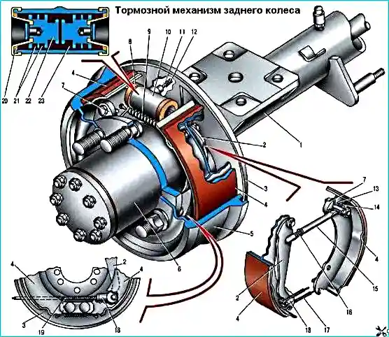
Rear wheel brake mechanism: 1 - rear axle; 2 - release lever; 3 - brake shield; 4 - brake shoe; 5 - brake drum; 6 - hub; 7 - eccentric; 8 - protective cap; 9 - upper tension spring; 10 - slave cylinder; 11 - air release valve; 12 - protective cap; 13, 14 - bushings; 15 - spacer bar; 16 - spring; 17 - lower tension spring; 18 - parking brake cable tip; 19 - parking brake cable; 20 - protective ring; 21 - cuffs; 22 - piston; 23 - piston thrust ring
Brake shoes 4 are driven by one hydraulic working cylinder 10 with two pistons 22.
The optimum clearance between the drum 5 and the shoes 4 is maintained by mechanical regulators located in the working cylinder and representing split steel elastic thrust rings 23 installed with tension in the cylinder.
The shaped tails of the pistons 22 enter the shaped holes of the thrust rings.
As the linings of the shoes wear out, the thrust rings move along the cylinder mirror to its outer holes, allowing the pistons to also move further outward and limiting their return movement into the cylinder under the action of the return springs, which compensates for the increasing gaps between the linings of the brake shoes and drum.

The pressure regulator during braking adjusts the brake fluid pressure in the working cylinders of the rear wheel brake mechanisms, eliminating the possibility of locking the rear wheels before the front ones.
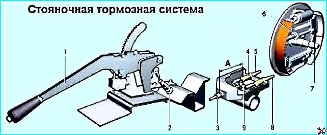
Parking brake system: A - control dimension (144-150 mm); 1 - parking brake drive lever; 2 - front cable; 3 - nuts; 4 - bracket; 5, 8 - rear cables; 6 - spacer bar; 9 - equalizer 7 - drive expansion lever
The regulator is fixed to the frame and reacts to the load perceived by the rear axle via a loading spring.
The parking brake system is mechanical, with a cable drive from the lever installed in the driver's cabin to the brake mechanisms of the rear wheels.
When lever 1 is acted upon, the brake shoes are pressed against the drums via a system of cables 2,5,8 and levers 7, braking the vehicle.
Lever 1 is fixed in the raised position using a ratchet mechanism consisting of a pawl and a toothed sector.
When the lever is raised, the switch located on the lever mounting bracket turns on the signal lamp in combination instruments.
The hydraulic brake system is connected into a single unit by metal tubes and hoses.
The system is filled with DOT-4 brake fluid.
The working stroke of the brake pedal with the engine running should be approximately 50 mm.
Too small a working stroke indicates an incorrect initial setting of the brake pedal, a violation of the adjustment of the brake booster or a jamming of the working cylinder, causes increased fuel consumption and accelerated wear of the brake pads.
Too large a working stroke is a sign of excessive clearances in the pedal mechanism or a violation of the tightness of the hydraulic drive of the brake system.
If the working stroke decreases with repeated pressing of the pedal, i.e. it becomes stiff, there is air in the system.
If the full pedal travel starts to increase, the system is leaky.
If the brake pedal always starts to vibrate when braking, most likely the brake discs are warped.
Unfortunately, in this situation, they only need to be replaced, and both at once.
If the car starts to pull to the side when braking, check the wheel cylinders: they may need to be replaced.
If a knock appears in the front suspension that disappears when braking, check the tightening of the caliper mounting bolts.
After replacing the brake pads, be sure to press the brake pedal several times before starting to move - the pistons in the wheel cylinders should fall into place.
In the variant version, the car is equipped with a brake system with automatic wheel locking (ABS)
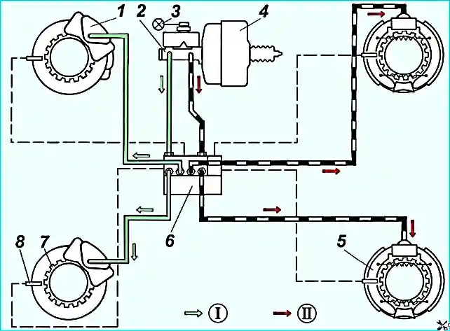
Diagram of the drive of the service brake system of cars with ABS: I - front brake circuit; II - rear brake circuit; 1 - front brake mechanism; 2 - master brake cylinder; 3 - emergency brake fluid level drop indicator; 4 - vacuum booster; 5 - rear brake mechanism; 6 - ABS hydraulic unit; 7 - rotor; 8 - ABS sensor
Possible brake system malfunctions and troubleshooting methods
- Cause of failure
Remedy
Increased brake pedal travel:
- Brake fluid leak from the working brake cylinders
Replace faulty brake cylinders, flush and dry the pads, discs and drums
- Air in the brake system
Bleed the air by bleeding the system
- Damaged rubber sealing rings in the master brake cylinder
Replace the cylinder assembly
- Damaged brake hydraulic hoses
Replace the hoses and bleed system
- Increased runout of the brake disc (more than 0.15 mm)
Grind or replace the disc if the thickness of the front brake discs is less than 30.0 mm.
Insufficient braking efficiency:
- Oiling of the brake pad linings
Wash and dry the pads
- Jamming of the pistons in the working cylinders
Eliminate the causes of jamming, replace damaged parts
- Complete wear of the brake pad linings
Replace the brake pads
- Overheating of the brake mechanisms
Stop and cool the brake mechanisms
- Use of substandard pads
Use original pads
- Breach of tightness of one of the circuits (accompanied by failure of the brake pedal)
Replace damaged parts, bleed the brake system
- Violation of the adjustment of the brake booster rod
Adjust the rod
Incomplete release of all wheels:
- No free play of the brake pedal
Replace the brake master cylinder
- Increased protrusion of the brake booster rod
Adjust the rod
- Swelling of the rubber seals of the master cylinder due to gasoline or oil ingress
Flush and bleed the entire hydraulic drive system, replace the rubber parts.
- Violation of the position of the front wheel brake caliper when loosening the bolts fastenings
Tighten the fastening bolts
- Incorrect adjustment of the parking brake system
Adjust the parking brake system
Skidding or pulling to the side when braking:
- Jamming of the piston of the working cylinder
Check and eliminate the jamming of the piston in the cylinder
- Clogging of the tube due to a dent or clogging
Replace or clean the tube
- Contamination or oiling of the discs, drums and linings of the brake shoes
Clean the brake mechanism parts
- Violated wheel alignment angles
Adjust the wheel alignment angles
- Different tire pressure
Set the required tire pressure
- One of the brake system circuits is not working
Replace damaged parts and bleed the system
Increased force on the brake pedal when braking:
- The vacuum booster is faulty
Replace the booster
- The hose connecting the vacuum booster is damaged or its fastening is loose
Replace the hose
- Swelling of the rubber cylinder seals due to substandard brake fluid
Replace the cylinders, flush and bleed the system
Squeaking or vibration of the brakes:
- Oiling of the friction linings
Clean with a wire brush with detergents and warm water
- Wear pads or foreign inclusions in them
replace the pads
- Excessive runout due to wear of the brake disc
Grind or replace the disc.

")
")
")
")
")
")
")
")