Check and adjust the wheel alignment angles on special stands according to the instructions for them.
Before adjusting the suspension, check:
- - air pressure in the tires;
- - free play of the steering wheel;
- - serviceability of the front suspension and steering drive parts.
Wheel alignment angles for a vehicle of unladen weight
Parameter - Angle
Longitudinal tilt angle of the steering axis of the wheel +3˚±1˚
The difference in the angles of the left and right wheels when adjusting the longitudinal tilt of the steering axis, no more than 0˚30′
Camber angle of each wheel 0˚30′±30′
Difference in angles left and right wheels when adjusting the camber, no more than 0˚30′
The angle of toe of each wheel to the longitudinal axis of the car is 0˚0′-0˚7′
After installing the car on the stand platform (immediately before measuring the wheel alignment angles), it is necessary to “squeeze” the suspension by briefly applying a force of 60-70 kgf from top to bottom.
If the angles do not correspond to the values specified in the table, they are adjusted in the following order:
- - the angle of longitudinal inclination of the wheel rotation axis;
- - camber angle;
- - toe angle.

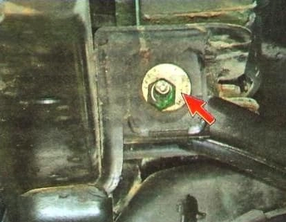
The longitudinal tilt angle of the steering axis is adjusted by changing the position of the front and rear adjusting bolts of the upper arm in the subframe brackets when they are turned in different directions by the same number of marks (or parts of marks) on the eccentric washers.
To make the adjustment, it is necessary to loosen the nuts of the adjusting bolts.

The main condition for adjustment is to ensure an angle difference of no more than 30’ between the left and right sides.
If it is impossible to set the longitudinal inclination specified in the table, only this condition is allowed to be met.
The camber angle is adjusted by changing the position of the front and rear adjusting bolts of the upper arm in the subframe brackets when they are turned in one direction by the same number of marks (or parts of marks) on the eccentric washers (see Table 2).
When only one adjusting bolt or both bolts are turned in one or different directions, but by a different number of marks (or parts of marks), both the camber angle of the wheel and the longitudinal inclination angle of the wheel pivot axis change.
After adjusting the longitudinal angle and camber angle of the wheels, tighten the nuts of the adjusting bolts of the upper arms to a torque of 120—160 Nm.
The toe-in angle is adjusted separately for the left and right wheels.
Preliminarily set and fix the steering wheel in the middle position (the spokes are horizontal).

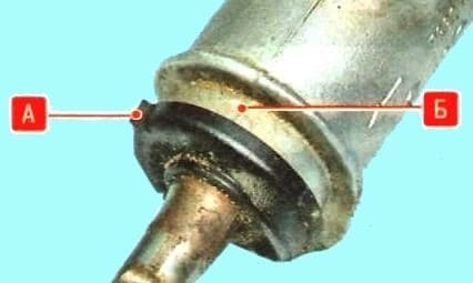
In this case, the steering gear should also be set to the middle position (mark "A" on the pinion shaft cover should match mark "B" of the injection mold connector on the distributor housing, a mismatch of no more than 2 is allowed. mm).
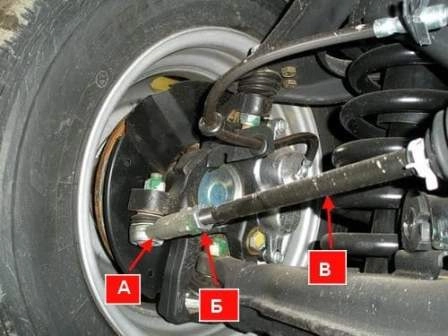
Loosen nuts "B" of tip "A" and, by rotating rods "B", set the required toe-in.

After completing the adjustment, holding rods "B" from turning, tighten nuts "B" with a second wrench to a torque of 65-78 Nm.
Changing the wheel alignment angles when turning the adjusting bolts


