Most electrical circuits are protected by fuses
Powerful consumers (rear window heating element, heater fan, engine cooling fan, air conditioning and others) are connected via a relay.
All relays (except for the heated rear window relay), power fuses and fuses for the engine management system are installed in the relay and fuse mounting block located in the engine compartment on the left, behind the battery.
The rest of the fuses are located in the fuse mounting block installed in the passenger compartment at the left end of the instrument panel.
The relay for turning on the heated rear window is installed on the cross member under the instrument panel.
If a fuse or relay is blown, you need to determine the cause of the burnout, only after the cause of the blowout has been eliminated, you can install the fuse or relay.
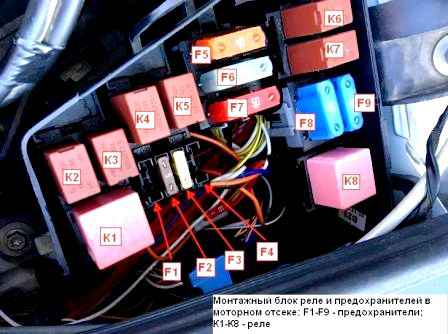
To replace the fuses of the mounting block in the engine compartment, disconnect the negative battery terminal
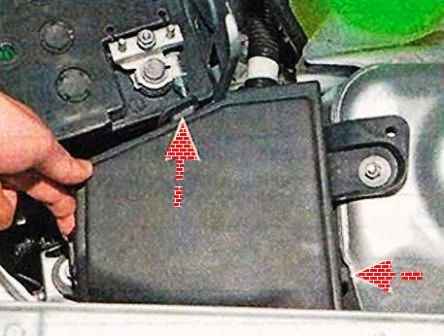
We press the three latches of the cover of the mounting block
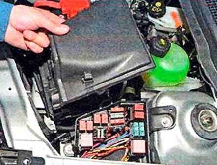
Remove the cover.
A faulty fuse is determined by a blown jumper.
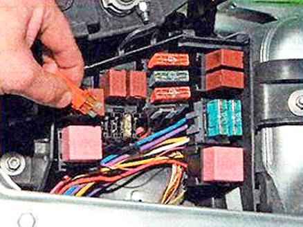
Retrieve small fuses with tweezers
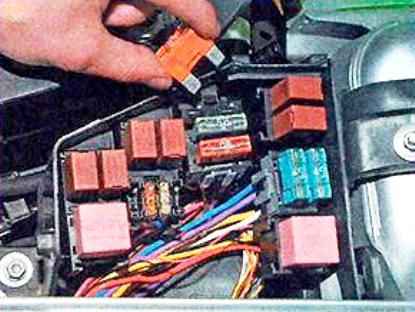
Large fuses can be removed by hand.
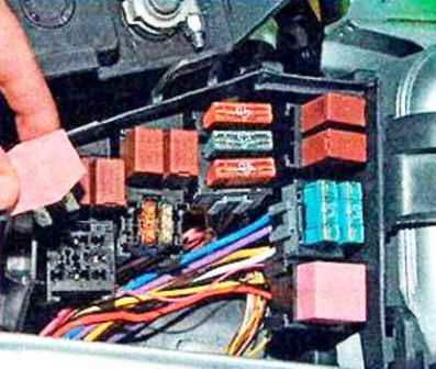
In the same way, we remove the relay from the mounting block
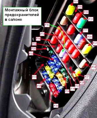
To access the fuse mounting block in the passenger compartment, pry off the cover of the block with your finger and, overcoming the resistance of the latches, remove the cover.
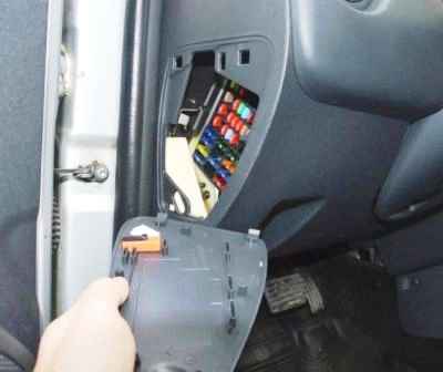
Remove the fuses from the block using tweezers.
Install new fuses and relays in reverse order.
Fuses in the passenger compartment
No. (current A) - Protected circuits
F01 (20) - Windshield wipers, rear window heating relay windings, switching unit
F02 (5) - Power supply of the instrument cluster, fuel pump relay windings and ignition coils, power supply
F03 (10) - Brake light circuits
F04 (10) - Direction indicators, diagnostic connector of the engine management system, immobilizer coil, switching unit
F06 (5) - Automatic transmission control unit circuit
F07 (10) - Reverse lamp circuits
F09 (10) - Dipped beam lamps of the left headlight, low beam signaling device in the instrument cluster
F10 (10) - Right headlight low beam lamp circuit
F11 (10) - High beam lamps of the left headlight, high beam signaling device in the instrument cluster
F12 (10) - High beam lamp circuit of the right headlight
F13 (30) - Front electric window circuits
F14 (30) - Rear electric window circuits
F15 (10) - ABS control unit circuit
F16 (15) - Seat heating for driver and front passenger
F17 (15) - Horn circuit
F18 (10) - Gauge lamps headlamp, left headlight, left tail lamp, license plate lamp
F19 (10) - Circuits: side light bulbs of the right headlight, side light bulbs of the right rear light, glove box lamp, illumination of the instrument cluster and controls, buzzer of the switching unit
F20 (7,5) - Circuits: lamp and rear fog lamp indicator
F21 (10) - Heated exterior mirror circuits
F23 (20) - Trailer electrical equipment
F26 (5) - Airbag control unit circuit
F27 (20) - Windshield washer circuit
F28 (30) - Heated rear window and door mirror circuit
F32 (15) - Circuits: interior dome light bulbs, trunk light bulbs, head unit constant power, instrument cluster
F33 (15) - Circuits: alarm, turn signal switch, intermittent windshield wiper, central locking control, engine management system diagnostic connector, switching unit
F34 (20) - Circuits: central locking, switching unit
F35 (15) - Fog lamp circuit
F36 (30) - Heater fan relay power circuit
F37 (5) - Exterior mirror electric circuits
F38 (15) - Circuits: cigarette lighter, radio power supply from the ignition switch
F39 (10) - Heater fan relay winding circuit
Fuses and relays of the mounting block in the engine compartment
No. (current) Circuit
F1 Not used
F2(5) Engine management ECU: main engine management relay coils
F3(25) Power circuits: fuel pump relay and ignition coils; main relay of the engine management system
F4(30) Cooling fan relay power circuit (non-air-conditioned car)
F5(40) Main Circuits: A/C Relay, Cooling Fan Low Speed Relay (A/C Car), Cooling Fan High Speed Relay (A/C Car)
F6(25) and F7(50) ABS circuits
F8(60) Circuits: power supply to all consumers, from the ignition switch, left-hand stalk
F9(60) Passenger compartment fuse box power supply circuit
Relay
K1 Cooling fan high speed relay (for cars with air conditioning). Cooling fan motor
K2 Air conditioning relay. Air conditioning compressor electromagnetic clutch.
K3 Cooling fan low speed relay (for cars with air conditioning) or cooling fan relay (for cars without air conditioning). Cooling fan motor (on a car with air conditioning - through a resistor)
K4 Fuel pump and ignition coil relay (fuel pump and ignition coils)
K5 Main relay of the engine management system (oxygen concentration sensors (heating circuit), fuel injectors, canister purge valve, relay coils K1, K2, K3, engine management ECU)
K6 Cigarette lighter relay
K7 Fog lamp relay (fog lamps)
K8 Heater fan relay (heater fan motor)


