
The front suspension is independent, MacPherson type, with triangular wishbones and anti-roll bar.
The basis of the suspension is a telescopic shock absorber strut, which allows the wheels to move up and down when driving through bumps and at the same time dampen body vibrations.
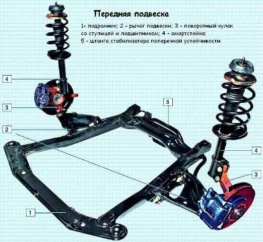
From below, the rack is attached with two bolts and nuts to the steering knuckle, and from above - with a nut through a rubber-metal support to the body.
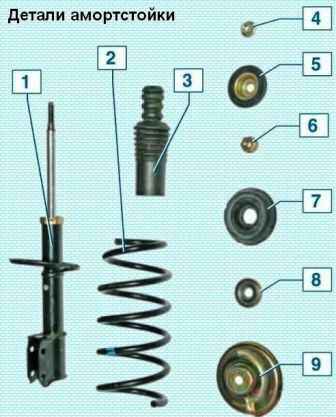
To effectively dampen body vibrations and improve vehicle handling and stability, a two-tube gas-filled shock absorber is installed in the strut body, which has higher characteristics than a conventional hydraulic shock absorber.
A lower spring support cup is welded to the middle part of the strut body, and a bracket for attaching the strut to the steering knuckle is welded to the bottom of the strut.
A compression stroke buffer is installed on the shock absorber rod, made integral with a protective cover.
From above, the spring rests against the upper support cup mounted on the shock absorber rod.
A thrust ball bearing is installed between the upper spring cup and the upper strut mount, allowing the strut body to rotate with the spring and the damper rod to remain stationary.
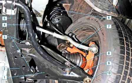
Braking and traction forces during vehicle movement are perceived by suspension arms connected through ball bearings to steering knuckles and through silent blocks with a subframe.
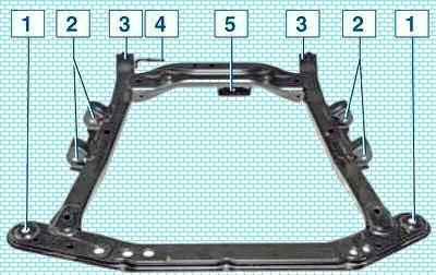
The subframe is rigidly attached to the body with four bolts, two rear bolts also attach the anti-roll bar brackets to the subframe.
At the end of the bolt of the front attachment of the suspension arm to the subframe, a subframe bracket is fixed with a nut, the other end of which is attached to the body.
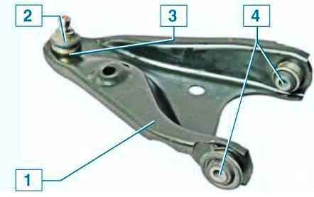
The body of the ball joint is pressed into the hole of the suspension arm, the ball joint is closed with a rubber boot.
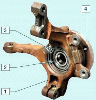
The ball joint pin is fastened with a clamp connection with a pinch bolt in the eye of the steering knuckle.
A closed-type double-row ball bearing is pressed into the hole of the steering knuckle, and the wheel hub is pressed into the inner bearing rings.
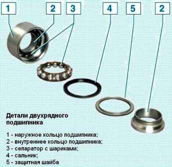
The inner rings are tightened through the hub with a nut on the threaded part of the shank of the wheel drive outer joint housing.
In operation, the bearing is not adjustable and does not require relubrication.
One of the two hub bearing shields is the front wheel speed sensor drive disk.
Nuts hub bearings of both wheels are the same, with right-hand thread.
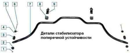
An anti-roll bar is installed on the car, which is designed to increase lateral stability and reduce body roll angles by twisting the middle part of the bar when moving its ends.
The anti-roll bar is made of spring steel.
The bar in its middle part is attached to the subframe with brackets through rubber cushions.
Both ends of the stabilizer bar are connected to the suspension arms through screws with rubber and rubber-metal bushings.
The angle of longitudinal inclination of the axis of rotation of the front wheel and the angle of camber of the wheel are set by design and cannot be adjusted in operation.
These angles can only be checked on a special stand (at a service station) and compared with control values.
If the values of the front wheel alignment angles do not correspond to the control values, it is necessary to check the condition of the front suspension elements.
Toe-in is adjusted by changing the length of the steering rods.
Possible malfunctions of the front suspension and methods of elimination
Cause of malfunction (Remedy)
Noise and knock in the suspension when the car is moving:
- Faulty suspension struts
Replace or repair racks
- - The bolts of the bracing brackets or the bolts of the anti-roll bar to the body have loosened.
- - Wear of rubber pads of stretch marks or rods
Tighten bolts, replace worn pads
- Loose fastening of the upper support of the suspension strut to the body
Tighten the top support nuts
- Settling, tearing, delamination of rubber from the rack support body
Replace the stand support
- Wear of rubber-metal hinges of suspension arms, stretch marks or stabilizer bar struts
Replace hinges
- Wear of the ball joint of the suspension arm
Replace ball joint
- Suspension spring settling or failure
Replace the spring
- Destruction of the compression stroke buffer
Replace Buffer
- Large wheel imbalance
Balance the wheels
- Shrinkage or damage to the O-ring of the strut housing (shock absorber reservoir)
Replace the ring
Frequent "breakdowns" of the suspension:
- Suspension spring sett
Replace the spring
Increased ball joint clearance:
- Wear of the rubbing surfaces of the parts of the ball joint as a result of contamination caused by leakage or damage to the boot
Replace ball joint
Moving the car away from straight ahead:
- Different air pressure in tires
Set normal pressure
- Violation of wheel alignment
Adjust wheel alignment
- Destruction of one of the upper suspension strut mounts
Replace the stand support
- Unequal elasticity of suspension springs
Replace the spring that has lost its elasticity
- Significant difference in tire wear
Replace worn tires
- Increased imbalance of the front wheels
Balance the wheels
Increased tire tread wear:
- Too sharp acceleration with wheel slip
Avoid sudden acceleration
- Frequent use of brakes with wheel lock
When braking, do not bring the wheels to block
- Violated wheel alignment
Adjust wheel alignment
- Vehicle overload
Do not exceed the allowable loads specified in the instruction manual
Uneven tire tread wear:
- Increased cornering speed
Slow down when cornering
- Large wear of ball joints of suspension arms and rubber-metal joints
Repair the suspension
- Wheel imbalance
Balance the wheels

")
")
")
")
")
")
")
")