• Home
    • Safety
    • Sitemap (en)
    • Mazda 6
    • Nissan Almera
    • Renault Sandero
    • Renault Arkana
    • Renault Megane 2
    • Renault Logan
    • Duster
    • GAZELLE NEXT
    • Solaris
    • UAZ car
    • Kia Magentis
  • Engines
  • transmission
  • Search

Repair Renault Megane-2

Renault Megane II

The Renault Megane II, produced from 2003 to 2008 in France, Turkey, and Spain, complies with European Euro 4 emissions standards.

The car was equipped with 1.4 L (K4J), 1.6 L (K4M), and 2.0 L (F4R) petrol engines, and a 1.5 L dCi diesel engine (K9K Turbo).

The cars were produced with front-wheel drive, with a 5- or 6-speed manual or 4-speed automatic transmission.

The body is all-metal, a load-bearing structure, and can be a four-door sedan, five-door station wagon, or hatchback.

In In 2006, the model underwent a minor restyling, which resulted in changes to the bumpers, radiator grille, and headlights.

The car was supplied to Russia in the following basic trim levels: Authentique, Sportway, Confort, Expression, ExTReme, Privilege, Dynamique, and Business.

Renault Megane II CO reduction system

General structure of the fuel vapour recovery system

The fuel vapour recovery system prevents the escape into the atmosphere, from the fuel system, of fuel vapours that adversely affect the ecology of the environment.

Renault Megane II Coolant Replacement

General requirements for the cooling system

Important! When performing work requiring complete draining of the fluid from the cooling system, always rinse the system with clean water and blow it through with compressed air to remove water residues.

Fill with coolant, remove the air from the system and measure its actual frost resistance. The system must ensure frost resistance:

  • at a temperature down to –25 °C ± 2 for countries with a cold and temperate climate;
  • at a temperature down to –40 °C ± 2 for countries with a very cold climate.

Precautions: before starting the work, cover the electrical equipment devices with plastic bags.

Replacing the coolant

Replacement interval: as recommended by the manufacturer, the coolant should be replaced after 6 years of operation or 90 000 km of mileage, whichever comes first.

Necessary materials and tools

  • coolant — use GLACEOL RX (type D);
  • clean cloth;
  • container for draining the coolant with a volume of at least 10 litres;
  • pliers.

Important! The coolant must be replaced with the engine cold.

Procedure

We place the vehicle on a lift or over an inspection pit.
Vehicle on the lift
We place the vehicle on a lift or over an inspection pit

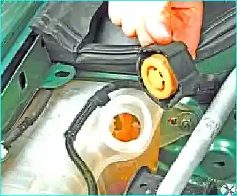
We open the expansion tank cap. We remove the engine undertray and the engine splash guard.
Removing the undertray and splash guard
We remove the engine undertray and the engine splash guard
Squeezing the clip ears of the expansion tank hose
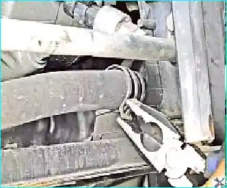
We squeeze the clip ears of the expansion tank supply hose securing clip and slide the clip along the hose

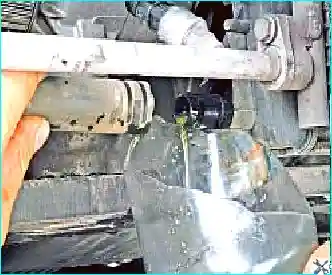
We remove the hose from the radiator stub and drain the fluid into the container placed underneath. After the coolant has finished draining, we refit the hose onto the stub.
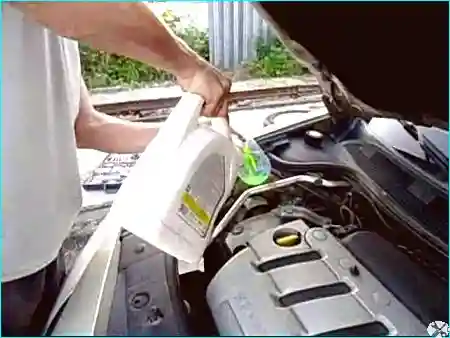
Pouring the coolant into the expansion tank
We pour the fluid into the expansion tank up to the «max» mark on the tank wall

Removing air locks

We start the engine and warm it up to operating temperature (until the fan switches on). After that we stop the engine and check the coolant level. If necessary, we top it up in the expansion tank to the «max» mark.

Temperature monitoring: while the engine is running, the coolant temperature must be monitored using the gauge.

If the gauge has reached the overheating zone but the radiator fan has not switched on:

  • switch on the heater and check what air passes through it;
  • if the heater supplies warmed air — the fan is most likely faulty;
  • if it supplies cold air — an air lock has formed in the engine cooling system.

To remove the air lock:

  1. We switch off the engine and let it cool down.
  2. We unscrew the filler neck cap.
  3. We start the engine and let it run for 3–5 minutes.
  4. We close the filler neck cap.

Tip: for better filling of the system without air locks, the radiator hoses should be periodically squeezed by hand.

After replacement: a few days after operating the vehicle following the coolant replacement, its level must be checked. If necessary, we top up the fluid.


Additional information: Method of replacing the coolant on a Renault Megane 2

Removing the intake and exhaust manifolds on the Renault Megane IIм

Removing and refitting the intake manifold (K4J engine)

Precautions: disconnect the leads from the battery terminals, starting with the negative terminal.

Preliminary operations:
  • Remove the air filter housing.
  • Remove the throttle body.
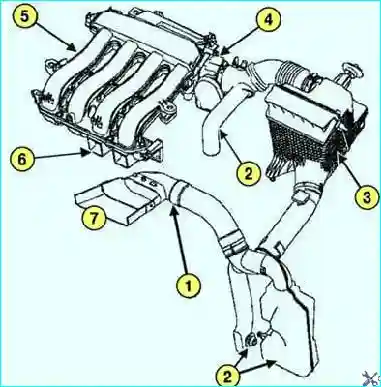
Diagram of the intake tract of the K4M engine
Fig. 1. Diagram of the intake tract (K4M engine): 1 — air intake duct; 2 — intake noise silencers; 3 — air filter housing; 4 — throttle body; 5 — intake manifold; 6 — injector body spacer; 7 — air intake
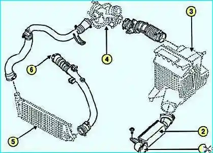
Diagram of the intake tract of the F4R engine
Fig. 2. Diagram of the intake tract (F4R engine): 1 — air intake; 2 — intake noise silencers; 3 — air filter housing; 4 — turbocharger; 5 — air cooler; 6 — intake distribution manifold inlet

Removal procedure

Removing the throttle assembly
Remove the throttle assembly
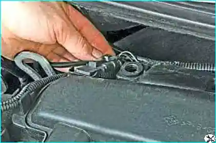
Pressing the fuel rail hose retainer
Press the retainer of the fuel rail hose end fitting
Disconnecting the hose from the fuel rail
Disconnect the hose from the fuel rail
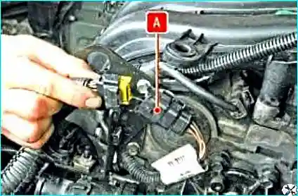
Disconnecting the injector wiring harness connector
Press the retainer of the wiring harness connector of the fuel injectors
Separating the wire connectors
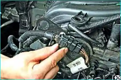
Separate the connectors and disconnect connector А from the bracket

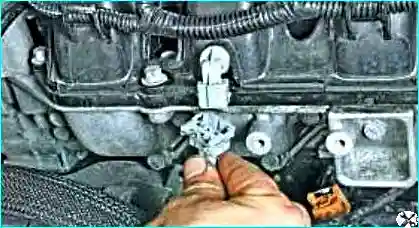
Press the retainer of the wiring harness connector of the pressure sensor in the receiver. Disconnect the connector from the sensor.

Disconnecting the air temperature sensor connector
Press the retainer of the wiring harness connector of the air temperature sensor in the receiver
Disconnecting the connector from the sensor
Disconnect the connector from the air temperature sensor
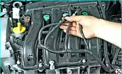
Disconnecting the connectors from the ignition coils
Disconnect the wiring harness connectors from the ignition coils
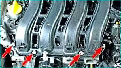
Unscrewing the receiver securing bolts
Unscrew the receiver securing bolts
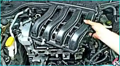
Removing the receiver
Remove the intake manifold receiver

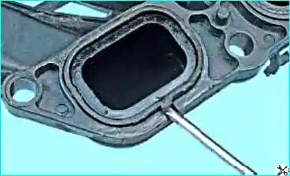
Note: prise up the sealing rings with a screwdriver and remove them. When refitting, replace the sealing rings.

Removing the fuel rail
Remove the fuel rail
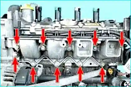
Unscrewing the intake pipe securing bolts
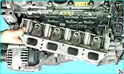
Unscrew ten intake pipe securing bolts
Removing the intake pipe
Remove the intake pipe
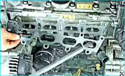
Removing the sealing gasket
Remove the intake pipe sealing gasket

Refitting

Important! All sealing gaskets are subject to mandatory replacement.

Tightening sequence of the intake manifold bolts
Fig. 5. Tightening sequence of the intake manifold securing bolts

Refitting is carried out in the reverse order to removal. Tighten in the sequence shown in Fig. 5 to the required torque the intake manifold securing bolts:

  • intake manifold securing bolts — 9 N·m;
  • throttle body securing bolts — 13 N·m;
  • air filter housing securing bolts — 9 N·m.

Reconnect the leads to the battery terminals, starting with the positive terminal.

Removing and refitting the intake manifold (K4M, F4R engines)

Precautions: disconnect the leads from the battery terminals, starting with the negative terminal.

Preliminary operations:
  • Remove the upper engine covers.
  • Remove the air duct.
  • Disconnect the wiring connector from the throttle body.
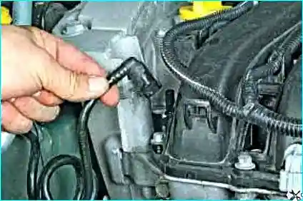
  • Disconnect the brake servo vacuum hose from the intake manifold.
  • Disconnect the fuel vapour recovery system pipeline from the throttle body.
  • Disconnect the wiring harness and move it aside.
  • Disconnect the fuel supply pipe from the fuel distribution rail.
  • Disconnect the fuel vapour control system pipeline from the intake manifold.

Attention: do not damage the vacuum take-off stub on the intake distribution manifold. If the stub is broken, replace the manifold.

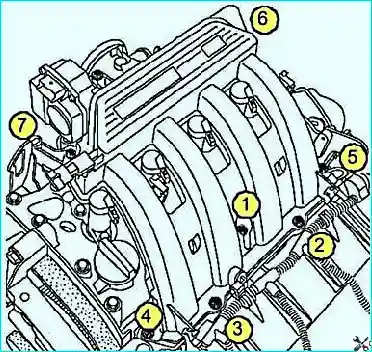
Removing the intake manifold of the K4M engine
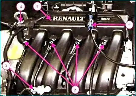
Removing the intake manifold of the K4M engine: 1 — throttle control cable; 2 — wiring harness connector to the ignition coils; 3 — wiring harness connector to the air temperature sensor; 4 — wiring harness connector to the intake air pressure sensor; 5 — intake manifold

Unscrew the intake manifold securing bolts. Remove the throttle body.

Important! All sealing gaskets are subject to mandatory replacement.

Tightening sequence of the intake manifold bolts K4M/F4R
Fig. 7. Tightening sequence of the intake manifold securing bolts

Refitting is carried out in the reverse order to removal. Tighten in the sequence shown in Fig. 7 to the required torque:

  • intake manifold securing bolts — 9 N·m;
  • throttle body with servo drive securing bolts — 13 N·m (uniformly and alternately).

Reconnect the leads to the battery terminals, starting with the positive terminal.

Removing and refitting the exhaust manifold (K4J, K4M engines)

Precautions: place the vehicle on a two-post lift. Disconnect the leads from the battery terminals, starting with the negative terminal.

Preliminary operations:
  • Remove the air filter housing (K4J).
  • Remove the intake manifold (K4M).
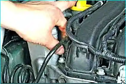
Disconnecting the lower oxygen sensor connector
Disconnect the wiring connector from the lower oxygen sensor
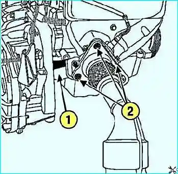
Unscrewing the nuts securing the receiving pipe flange
Unscrew the nuts securing the receiving pipe flange of the exhaust pipeline and remove the exhaust manifold strut

Mark with a marker the position of the exhaust pipeline suspension cushion brackets on the body.
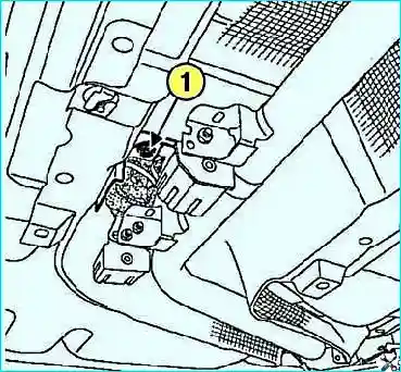
Unscrewing the suspension cushion bracket securing bolt
Unscrew the bolt securing the exhaust pipeline suspension cushion bracket to the body
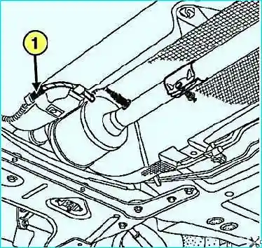
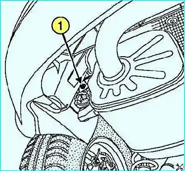
Unscrewing the main silencer bracket securing bolt
Fig. 11. Unscrewing the securing bolt of the main silencer suspension cushion bracket: 1 — bolt

Move the exhaust pipeline rearwards. Remove the oxygen sensor using the tool (Mot1495-01).
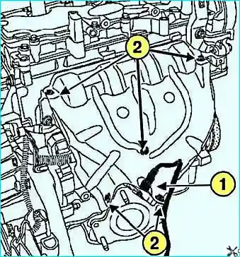
Removing the upper heat shield
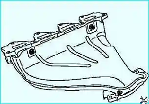
Remove the upper heat shield of the exhaust manifold
Unscrewing the nuts of the exhaust manifold securing studs
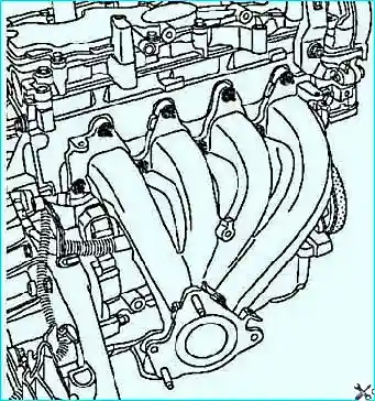
Unscrew nine nuts of the securing studs and remove the exhaust manifold
Removing the lower heat shield
Fig. 14. Removing the heat shield

Subject to mandatory replacement:

  • manifold gaskets;
  • exhaust pipeline flange gaskets;
  • nuts of the exhaust manifold securing studs.
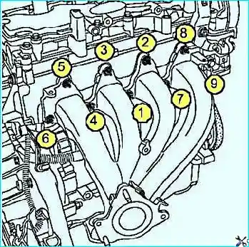
Tightening sequence of the exhaust manifold nuts K4J/K4M
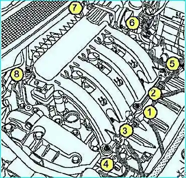
Fig. 15. Tightening sequence of the exhaust manifold securing nuts

Refitting is carried out in the reverse order to removal. Tighten in the sequence shown in Fig. 15 to the required torque:

  • nuts of the exhaust manifold securing studs — 23 ± 3 N·m;
  • heat shield securing bolt — 10 N·m;
  • oxygen sensors — 45 N·m;
  • bolts securing the exhaust pipeline suspension cushion brackets to the body — 21 N·m;
  • strut securing bolt on the exhaust manifold — 8 N·m;
  • exhaust pipeline flange securing nuts — 20 N·m.

Reconnect the leads to the battery terminals, starting with the positive terminal.

Removing and refitting the exhaust manifold (F4R engine)

Precautions: disconnect the leads from the battery terminals, starting with the negative terminal. Remove the power unit and the turbocharger.

Important! When removing and refitting the turbocharger, the repair procedure must be strictly followed to ensure the tightness of the system. Failure to follow these instructions may result in reduced driver safety.
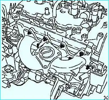
Removing the exhaust manifold of the F4R engine
Fig. 16. Removing the exhaust manifold

Unscrew the nuts of the securing studs and remove the exhaust manifold.
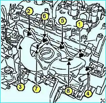
Tightening sequence of the exhaust manifold nuts F4R
Fig. 17. Tightening sequence of the exhaust manifold securing nuts

Refitting is carried out in the reverse order to removal. Tighten in the sequence shown in Fig. 17 to the required torque of 20 N·m the nuts of the exhaust manifold securing studs.

Refit the turbocharger and the power unit.

Renault Megane II body structure

General body structure

The body of the Renault Megane 2 vehicle is of load-bearing construction, of the four-door saloon, five-door hatchback or five-door estate type. The body consists of a framework and bolt-on assemblies.
Removing Renault Megane II seat belts

Tools: 16 mm spanners, TORX T15, flat-blade screwdriver.

  • 1
  • 2
  • 3
  • 4
  • 5
  • 6
  • 7
  • 8
  • 9
  • 10

Select your language

  • 正體中文
  • French (fr-FR)
  • Беларуская (Беларусь)
  • Deutsch (Deutschland)
  • Russian (ru-RU)
  • Українська (Україна)
  • Қазақша (kk-KZ)
  • English (UK)
  • Español (España)