
The front suspension is independent, MacPherson type, with triangular wishbones and anti-roll bar.
The basis of the suspension is a telescopic shock absorber strut, which allows the wheels to move up and down when driving through bumps and at the same time dampen body vibrations.
From below, the rack is attached with two bolts and nuts to the steering knuckle, and from above - with a nut through a rubber-metal support to the body.
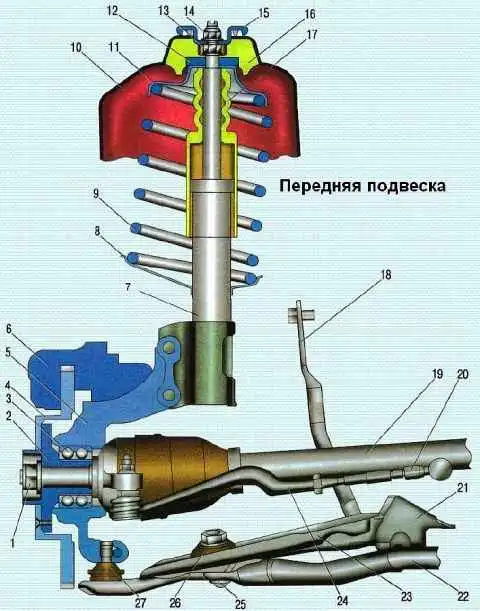
To effectively dampen body vibrations and improve vehicle handling and stability, a two-tube gas-filled shock absorber is installed in the strut body, which has higher characteristics than a conventional hydraulic shock absorber.
A lower spring support cup is welded to the middle part of the strut body, and a bracket for attaching the strut to the steering knuckle is welded to the bottom of the strut.
A compression stroke buffer is installed on the shock absorber rod, made integral with a protective cover.
From above, the spring rests against the upper support cup mounted on the shock absorber rod.
A thrust ball bearing is installed between the upper spring cup and the upper strut mount, allowing the strut body to rotate with the spring and the damper rod to remain stationary.
Braking and traction forces during vehicle movement are perceived by suspension arms connected through ball bearings to steering knuckles and through silent blocks with a subframe.
The subframe is rigidly attached to the body with four bolts, two rear bolts also attach the stabilizer bar brackets to the subframe (the stabilizer bar is installed only on modifications with the K4M engine).
At the end of the bolt of the front attachment of the suspension arm to the subframe, a subframe bracket is fixed with a nut, the other end of which is attached to the body.
The body of the ball joint is pressed into the hole of the suspension arm, the ball joint is closed with a rubber boot.
The ball joint pin is fastened with a clamp connection with a pinch bolt in the eye of the steering knuckle.
A closed-type double-row ball bearing is pressed into the hole of the steering knuckle, and the wheel hub is pressed into the inner bearing rings.
The inner rings are tightened through the hub with a nut on the threaded part of the shank of the wheel drive outer joint housing.
In operation, the bearing is not adjustable and does not require relubrication.
One of the two hub bearing shields is the front wheel speed sensor drive disk. The hub bearing nuts of both wheels are the same, with right-hand threads.
An anti-roll bar is installed on a car with a K4M engine.
The stabilizer is designed to increase lateral stability and reduce body roll angles by twisting the middle part of the bar when moving its ends.
The anti-roll bar is made of spring steel.
The bar in its middle part is attached to the subframe with brackets through rubber cushions.
Both ends of the stabilizer bar are connected to the suspension arms through screws with rubber and rubber-metal bushings.
The angle of longitudinal inclination of the axis of rotation of the front wheel and the angle of camber of the wheel are set by design and cannot be adjusted in operation.
These angles can only be checked on a special stand (at a service station) and compared with control values.
If the values of the front wheel alignment angles do not correspond to the control values, it is necessary to check the condition of the front suspension elements.
Toe-in is adjusted by changing the length of the steering rods.
Possible malfunctions of the front suspension and solutions
Cause of malfunction - Remedy
Noise and knocking when the car is moving:
Loosening of the attachment to the rear of the subframe of the brackets of the anti-roll bar of the car and its struts to the shock absorber suspension strut - Tighten loose screw connections
Wear of rubber parts of the stabilizer and its struts - Replace worn parts
Top mount rubber wear - Replace strut top mount
Ball joint wear - Replace arm
Worn tie rod joints - Replace tie rod end
Worn front wheel bearings or loose hub nut - Replace bearing or retighten nut
Front suspension spring failure - Replace springs
Shock absorber compression buffer failure - Replace compression buffer
Avoiding a car from a straight line on a horizontal road:
Misaligned Front Wheel Alignment - Eliminate Causes of Misaligned Wheel Alignment and Adjust Wheel Alignment
Uneven spring settlement - Replace front suspension springs
Increased or uneven tire tread wear:
The angles of the front wheels are violated - Adjust the angles
Increased wear on suspension or tie rod joints - Replace suspension or tie rods
Suspension strut malfunction - Replace shock struts
Checking the technical condition of the front suspension
We install the car on a lift or an inspection ditch and hang out the front wheels.
Suspensions on rubber parts are not allowed:
- - signs of rubber aging;
- - mechanical damage.
On rubber-metal hinges are not allowed:
- - signs of aging, cracks, one-sided swelling of the rubber array;
- - separation of the rubber array from the armature.
We pay special attention to mechanical damage (deformations, cracks, etc.) of the suspension elements, especially the levers.

Checking the condition of the protective covers of the ball bearings.
If the covers are damaged, we replace the ball joints as an assembly.

Swinging the wheel in a vertical plane, we check the ball joints for backlash.
If there is play in the ball studs, replace the lower arm assembly.
When swaying a suspended wheel, it is difficult to distinguish play in the hub bearings and play in the ball bearings.
Have an assistant press the brake pedal; if in this case you feel a backlash, then the ball joints are faulty.

Check the rubber bushings and silent blocks in the places where the levers are attached to the body.

Checking the condition of the rubber bushings at the attachment points of the anti-roll bar (on vehicles equipped with a stabilizer) to the suspension arms

Check the condition of the stabilizer rubber pads in the places where the rod is attached to the subframe.
Checking the condition of the shock strut protective cover.

")
")
")
")
")
")
")
")