In the article, we will consider repairing a clutch with a manual transmission of a car.
Removing and installing the clutch
When replacing the clutch, it is recommended to replace the entire clutch kit.
You will need a tool that is used when removing the gearbox, as well as a key for 11, a screwdriver;
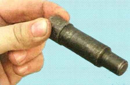
- you will need a mandrel to center the driven disk (suitable from VAZ).
We install the car on a viewing ditch or lift
Removing the gearbox (article - Removing a manual transmission of a Renault Sandero)
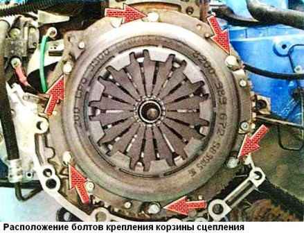
The clutch cover is attached to the flywheel with six bolts
When installing an old basket, note the position of the basket relative to the flywheel to maintain balance.
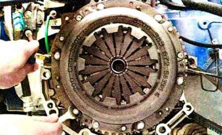
We unscrew the six bolts securing the basket, holding the flywheel from turning with a mounting blade.
Weaken the bolts evenly over one turn of the wrench, moving from bolt to bolt in diameter.
When loosening tightly, you can tap the bolt heads with a hammer.
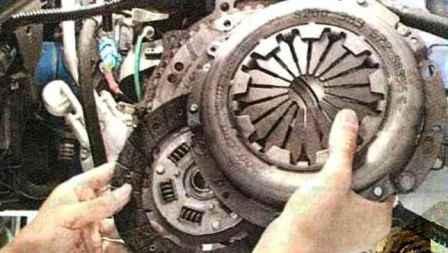
Remove the basket and clutch disc from the flywheel, holding the clutch disc
After removing the clutch, inspect the clutch disc.
Cracks on the parts of the driven disk are not allowed.
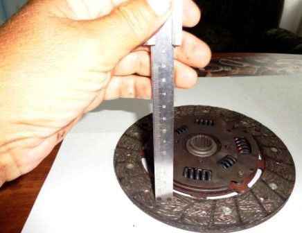
Check the degree of wear of the friction linings.
If the rivet heads are sunk by less than 0.2 mm, the lining surface is oily, or the rivet connections are loose, then the driven disk must be replaced.
If the lining of the driven disk is oily, you need to check the oil seal of the gearbox input shaft.
It may need to be replaced.
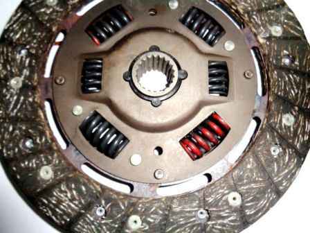
We check the reliability of fixing the damper springs in the sockets of the hub of the driven disk, trying to move them by hand in the sockets of the hub.
If the springs move easily in their sockets or are broken, replace the disc.
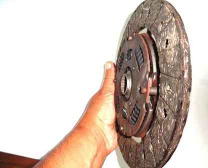
Check the axial runout of the driven disk, if its warping is detected during external examination.
If the runout exceeds 0.5 mm, replace the disc.
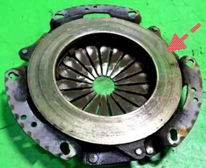
We inspect the working friction surfaces of the flywheel and pressure plate, paying attention to the absence of deep scratches, scuffs, nicks, obvious signs of wear and overheating.
Replacing defective nodes.
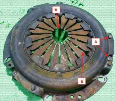
When loosening the rivet connections "A" of the parts of the casing and the pressure plate, we replace the pressure plate.
With an external inspection, we evaluate the condition of the diaphragm spring "B" of the pressure plate.
Cracks on the diaphragm spring are not allowed.
Places "B" of contact between the petals of the spring and the release bearing should be in the same plane and not have obvious signs of wear (wear should not exceed 0.8 mm).
Otherwise, replace the discs as an assembly.
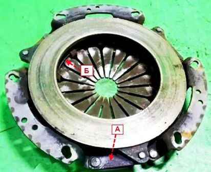
We examine the connecting links "A" of the casing and the disk.
If the links are deformed or broken, replace the pressure plate assembly.
We evaluate the condition of the support rings "B" of the pressure spring by external inspection.
Rings must be free of cracks and signs of wear.
Before installing the clutch, we check the ease of movement of the driven disk along the splines of the gearbox input shaft.
We apply refractory grease to the splines of the driven disk hub
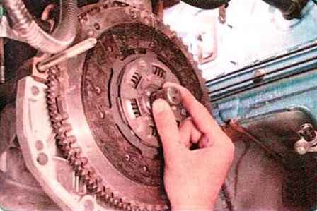
When installing the clutch, first install the driven disk using a mandrel
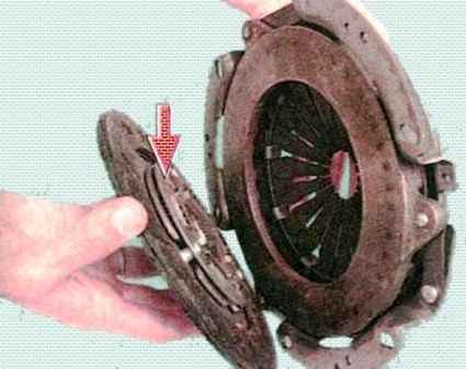
We install the driven disk so that the protruding part of the disk hub (shown by the arrow) is directed towards the diaphragm spring of the clutch housing.
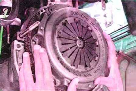
After that, install the clutch basket on three centering pins and screw in the bolts securing the casing to the flywheel.
We screw the bolts evenly, one turn of the wrench each, alternately moving from bolt to bolt in diameter. Bolt tightening torque 12 Nm (1.2 kgcm).
Remove the mandrel and install the gearbox.
We install the lower end of the clutch release cable on the gearbox and adjust the length of the threaded end of the cable (as described below).
Replacing the bearing and the clutch release fork
Increased noise when the clutch is released, while pressing the pedal, is a sign that the release bearing needs to be replaced.
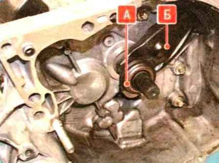
The release bearing "A" complete with the clutch (Fig. 1) is mounted on the guide sleeve and connected to the clutch release fork "B".
The fork is inserted with its pins and rests on a ball joint screwed into the clutch housing.
The fork is fixed by its corrugated rubber boot inserted into the window of the clutch housing.
To remove the release bearing, remove the gearbox (article - Removing the manual transmission of a Renault car Sandero)
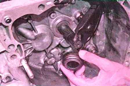
Moving the release bearing along the guide sleeve forward, we remove the sleeve from the grooves of its clutch and remove the bearing.
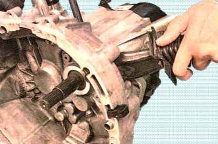
If it is necessary to remove the clutch release fork, remove its cover from the hole in the clutch housing and remove the fork from the ball joint
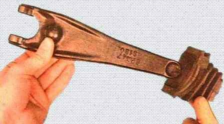
If necessary, remove the dirt cover from the plug
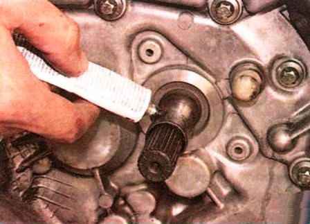
Lubricate the outer surface of the guide bush with a thin layer of refractory grease
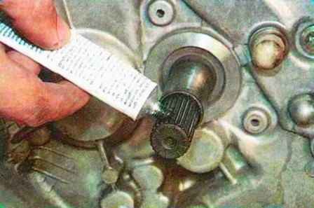
Lubricating the splines of the gearbox input shaft
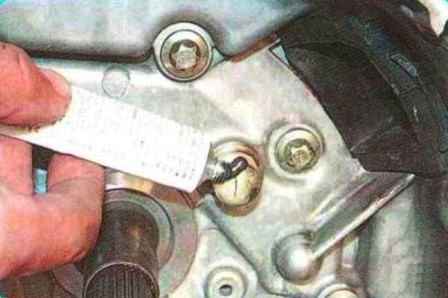
Lubricating the ball joint of the clutch release fork
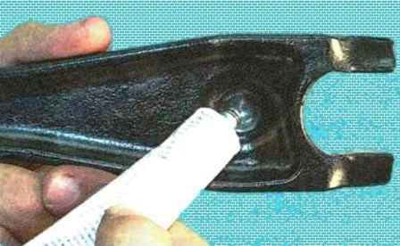
Lubricate the surface of the fork in contact with the ball joint
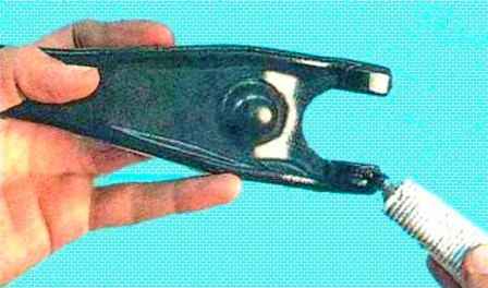
Lubricating the legs of the fork
Install the fork and release bearing in reverse order.
Additional fixation of the release fork on the release bearing clutch and ball joint is not provided.
Therefore, after installing the yoke and bearing, do not rotate the yoke in a vertical plane, as it may disengage from the grooves of the coupling.
Replacing and adjusting the clutch cable
Before removing the cable, we measure the length of the free threaded part of the lower end of the cable at the gearbox.
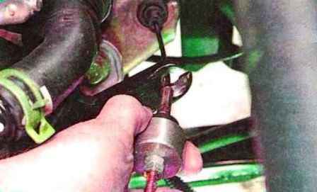
Sliding the cable forward, we remove its tip from the slot of the clutch release fork
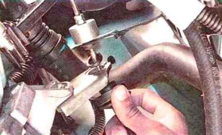
Remove the cable sheath damper from the bracket on the gearbox housing
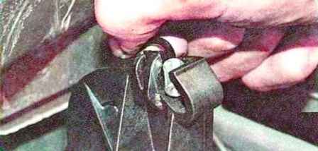
Disconnect the tip of the cable from the sector of the clutch pedal
We remove the cable sheath from the stop in the bulkhead shield and remove the cable, pulling it out of the shield into the engine compartment
Install the clutch cable in reverse order
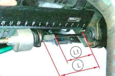
After installing the cable, we perform the initial installation of the cable.
We measure the dimensions L and L1, respectively, between the end of the damper and the clutch release fork, as well as between the end of the damper and the tip of the cable.
Dimension L should be (86±) mm, Dimension L1 should be (60±5) mm.
If the dimensions do not correspond to the specified ranges of values, set them by turning the adjusting nut of the cable end with the locknut loosened.
As the lining of the clutch disc wears out during operation, the initial setting of the clutch release cable also changes.
This moves the clutch pedal up, increases its full travel and delays the clutch engagement at the very end of the pedal stroke.
In this case, check and restore the initial setting of the cable with the adjusting nut on its threaded end.
Depress the clutch pedal three times to the stop and re-measure the distance L and L1.
Re-adjust if necessary.
We check that the travel of the free end of the clutch release fork is within 28-33 mm for clutching a 1.4-liter engine and 30-35 mm for a 1.6-liter engine.
Repair of the pedal assembly
Clutch pedal made of plastic.
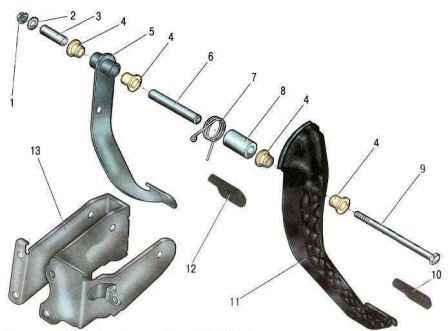
It is mounted on the same axle as the steel brake pedal.
Axle 9 is fixed with nut 1 in bracket 13 mounted on the front end shield of the body.
To return the pedal to its original position, spring 7 is installed.
The pedals are mounted on the axle through plastic bushings.
If there is a squeak or jamming of the pedals, you need to disassemble the pedal assembly and repair it.
You will need two keys for 13.
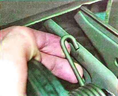
We disengage the bent end of the clutch pedal return spring from the edge of the pedal assembly bracket
Disconnect the clutch release cable from the clutch pedal sector
Disconnect the pusher of the vacuum brake booster from the brake pedal
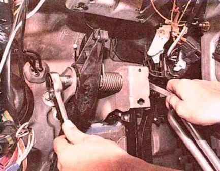
We unscrew the nut 1 (Fig. 1) securing the pedal axle, holding the axle from turning with the second key.
We remove the axle from the holes of the pedals and the bracket, alternately removing the remote bushing 3, the brake pedal 5 complete with bushings 4, the remote bushing 6, the spring 7, the remote bushing 8 and the clutch pedal 11 assembly with bushings 4 from the axle.</ p>
We take out the plastic bushings from the holes of the pedals 4. Replace the worn bushings.
We assemble the pedal assembly in the reverse order.


