
A four-speed DPO automatic transmission is available on select vehicle options to provide the optimum gear selection for virtually all driving styles and road conditions

The automatic transmission is arranged according to the traditional planetary circuit with friction braking and is connected to the engine crankshaft through a torque converter.
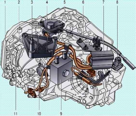
Automatic transmission: 1 - valve block cover; 2 - planetary gear housing; 3 - bracket for the left suspension support of the power unit; 4 - mode selection switch; 5 - torque converter housing; 6 - automatic transmission control cable; 7 - electronic control unit; 8 - speed sensor; 9 - working fluid heat exchanger; 10 - valve for controlling the flow of liquid through the heat exchanger; 11 - rear cover of the planetary gear
An electronic automatic transmission control system constantly monitors vehicle speed and engine load, eliminating driver error by preventing the driver from upshifting at low speed to avoid engine overload, or downshifting at too high a speed, which eliminates the possibility of exceeding the maximum allowable engine speed.
When the vehicle speed decreases, the gears automatically shift to lower gears without driver intervention.
When the car comes to a complete stop, 1st gear is automatically engaged.
The automatic transmission consists of a torque converter, a pump, a planetary gear, multi-disc clutches, multi-disc brakes and a valve block.
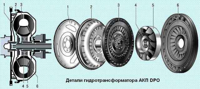
The torque converter performs the functions of a clutch and serves to smoothly connect the engine to the gearbox mechanism and increase torque when the car starts moving.
The torque converter housing is connected to the engine crankshaft through the drive plate and rotates constantly when the engine is running.
The inside of the torque converter is filled with automatic transmission fluid.
The engine turns the torque converter and drives the pump wheel, which creates flows of working fluid in the direction of the turbine wheel.
The turbine wheel begins to rotate due to the flow of working fluid created by the pump wheel.
With a large difference in the speeds of rotation of the turbine and pump wheels, the reactor changes the direction of the fluid flow, increasing the torque.
As the speed difference decreases, it becomes unnecessary and is therefore installed on the freewheel.
A pump mounted in front of the gearbox housing pressurizes and supplies fluid to all systems in the gearbox.
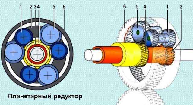
The planetary gearbox is a gear train with external and internal gears, which provides various ways to connect its elements to obtain various gear ratios.
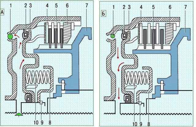
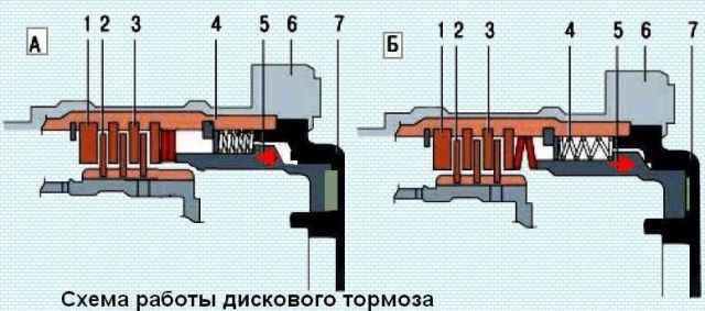
Scheme of operation of a multi-plate clutch: A - multi-plate clutch is on; B - multi-plate clutch is off; 1 - ball valve; 2 - sealing ring; 3 - piston; 4 - friction disc; 5 - friction disc with pads; 6 - thrust disk; 7 - clutch hub; 8 - spring stop; 9 - retaining ring; 10 - return spring
The principle of operation of multi-plate clutches and disc brakes is very similar, the difference lies in the fact that the multi-plate clutch connects the gearbox links to each other, and the disc brake connects to the crankcase ohm box.
The working fluid supplied to the clutch actuates the piston, and the friction discs are compressed.
The links blocked by the clutch begin to rotate as one.
When the disc brakes are released, the working fluid stops flowing into the clutch and the piston returns to its original position under the action of the return spring.
The design feature of a multi-plate clutch is that it is in constant rotation and under the action of centrifugal force acting on the working fluid, pressure is created that prevents the clutch from unlocking.
In addition, a ball valve is installed in the coupling.
It is located as close to the edge as possible from the center of the coupling.
When the pressure of the working fluid in the chamber of the multi-plate clutch increases, the ball valve closes the drain hole, and when the pressure in the chamber decreases, the ball valve opens the drain hole under the action of centrifugal force and the clutch unlocks.
The automatic transmission control drive is cable-operated, designed on the same principle as the manual transmission control drive, but differs from it in the number and design of parts.
The automatic transmission selector is installed in the same place on the floor tunnel as the manual transmission control lever and is connected to the control unit on the transmission with a cable.
An automatic transmission differential is identical in design to a manual transmission differential.
The differential housing has two sealed holes for the output shafts, which allows you to dismantle the gearbox without draining the working fluid.