The electrical equipment of the car is made according to a single-wire circuit: the negative terminals of sources and consumers of electricity are connected to the body and other units of the car, which act as a second wire
Scheme of electric equipment of UAZ car -31514, -31519
Scheme of the electrical equipment of the UAZ-31512 car
On-board network - direct current, with a nominal voltage of 12 V.
To switch the main circuits of the car, a combined ignition switch is used, consisting of a contact part and a mechanical anti-theft device with a lock
When the engine is not running, all consumers are powered by the battery, and after the engine is started, they are powered by an alternator with a built-in rectifier unit. When the generator is running, the battery is charged.
When the engine is idling, the generator rotor speed and, accordingly, the output current are insufficient to provide power to powerful consumers (headlights, windshield wiper, heater fan, alarm). In this mode, the battery will be discharged.
To protect the electrical circuits of the car's exterior lighting from overload, a bimetallic fuse is used, which is installed under the instrument panel on the left.
Three 10A fuses are installed in a block mounted on the bulkhead of the engine compartment
They protect:
- No. 1 - chains of control devices;
- No. 2 - direction indicator chains;
- No. 3 - alarm and horn circuits.
Fuse number 1 is located closer to the starboard side of the car
The heater fan motor power circuit is protected by a 6A fuse.
The fuse is attached to the wiring harness next to the heater switch
The car may be equipped with other additional fuses, depending on the equipment.
When repairing electrical equipment, disconnect the battery with a ground switch or remove the terminals from its terminals.
Checking electrical circuits
To measure electrical parameters, a digital or analog (pointer) tester is used - a voltmeter, ohmmeter and other devices combined in one housing.
Digital devices have a low inertia, they are insensitive to vibrations and the position of the body during measurements, but the arrows more clearly show the dynamics of changes in the measured parameters
In addition, the liquid crystal display of digital instruments is sensitive to sunlight and elevated temperatures
Checking dead circuits
Before work, we calibrate the ohmmeter. At the selected measurement limit (for most circuits up to 200 Ohm), close the probe tips
On an analog device, set the arrow to zero with the “0” setting knob. There is no such regulator in household digital appliances.
Therefore, before measuring small values (up to 1–2 ohms), by shorting the probes, we determine the internal resistance of the ohmmeter and its wires, which is 0.03–0.06 ohms.
This value must be subtracted from the resulting resistance value.
To check the circuit, disconnect at least one of its ends (otherwise, the current will bypass, in other parts of the circuit, and the readings will be incorrect).
It is better to put a crocodile clip on one of the probes and connect it to the ground
When checking devices with one-sided conduction (for example, the rectifier unit of a generator), consider the polarity of the device.
For checking starter windings, alternator windings, high voltage wires, etc. switch the device to the lower limit of measurements
In practice, the accuracy of conventional autotesters is not enough to check circuit sections where even the slightest increase in resistance is unacceptable, for example, due to poor contact.
Therefore, we pay attention to slight deviations of the arrow from zero division, and after the measurement, we check the calibration of the devices again.
We check the short circuit of the winding to the “case” and the interturn short circuit with a megohmmeter (range “M”).
Many testers (pointers) require an additional DC source when operating in this range.
In its absence, being careful, we check the circuit with a lamp powered by 220 V.
Checking live electrical circuits
We check energized circuits with a voltmeter and ammeter
We connect the voltmeter in parallel with the device under test or section of the circuit. Measuring range 0-15 or 0-25 VDC.
We connect the negative wire (probe) to ground, the positive wire to consumers or sources current.
According to the voltage drop, you can determine the malfunction of the supply circuit (breakage, oxidation of contacts, etc.), as well as a short circuit in the consumer.
To check live circuits, you can use a test lamp with a power of no more than 3-4 W, rated for a voltage of 12 V (for example, an AMH12-3 lamp used in the instrument cluster).
The ammeter must have an upper measurement limit of at least 10 A DC, as well as overload protection.
We connect the ammeter in series with the device under test. We connect the "plus" of the device to the current source, and the "minus" - to the "plus" of the consumer
We measure the consumed current and compare it with the nominal current indicated in the technical specification of the device under test.
Since the actual voltage in the on-board network differs from the nominal one (in the reference data, the rated current corresponds to the rated voltage, i.e. 12 V), the value obtained may differ slightly from the indicated one
If the current is less than required, then the electrical circuit is faulty, and if more, there is a short circuit in the consumer
Battery
A 6CT-60 lead starter battery is installed on cars.
The battery consists of six series-connected batteries placed in separate compartments of a common body (positive and negative lead plates are separated by separators)
The compartments are filled with an electrolyte - a solution of sulfuric acid in distilled water, with a density of 1.27–1.28 g/cm3.
Technical characteristics of the battery 6ST-60
Rated voltage, V 12
Capacity at 20-hour discharge and electrolyte temperature +25° С, A.h 60
Volume of electrolyte, l 3.6
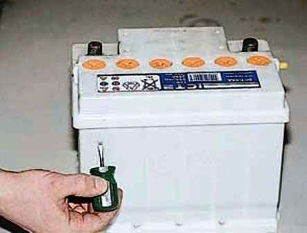
When servicing the battery, check the electrolyte level and density.
If the electrolyte level has dropped, add distilled water or electrolyte in case of leakage

In this case, we are guided by the marks of the permissible electrolyte level on the battery case or the lower edge of the filler hole.

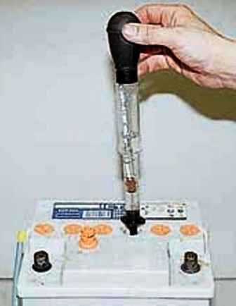
We measure the density with a hydrometer.
In this case, please note that until the water is completely mixed with the electrolyte, the hydrometer readings will be underestimated.
The degree of charge of the battery can be indirectly determined by the voltage at its terminals.
Voltage "V" - The degree of charge of the battery, batteries, "%"
- 12.6 - 100
- 12.0 - 75
- 11.6 - 50
- 11,3 - 25
- 10.5 - 0
We wipe the outer surfaces of the battery with a rag moistened with a solution of baking soda or ammonia.
Strictly observe the safety regulations when handling the battery. Systematically check the reliability of the fastening of the terminals on the battery terminals.
To protect against oxidation, lubricate them with any grease
Possible battery problems and solutions
Battery drains quickly
- Long driving with the headlights on and the heater electric motor at low speed, as well as frequent use of headlights in parking lots with the engine off
Turn off current consumers when the car stops
- Malfunction of the generator or voltage regulator
Check generator and regulator.
If necessary, replace defective units
- Malfunction of one or all battery cells
Replace defective battery
- Electrolyte contamination
Replace electrolyte
The electrolyte level in the battery drops quickly
- Electrolyte boiling
Check the voltage regulator, if necessary, replace it


