The parts of the connecting rod and piston group are divided into categories and are selected individually for each other
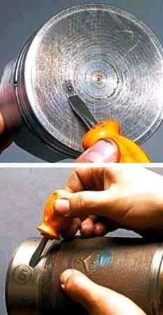
The tolerance group marked with a letter and stamped on the piston crown must match the group indicated on the cylinder liner
Dimensional groups of pins, pistons and connecting rods
| Diameter, mm | Marking | |||
|---|---|---|---|---|
| Fingers | Hole | pin and connecting rod | piston | |
| In Piston Boss | In the connecting rod hub | |||
| 25.0000-24.9975 | 25.0000-24.9975 | 25.0000-24.9975 | white | I |
| 24.9975-24.9950 | 24.9975-24.9950 | 25.0045-25.0020 | green | II |
| 24.9950-24.9925 | 24.9950-24.9925 | 25.0020-24.9995 | yellow | III |
| 24.9925-24.9900 | 24.9925-24.9900 | 24.9995-24.9970 | red | IV |
The values of the diameters of the holes in the piston bosses, the connecting rod head and the outer diameters of the piston pin are divided into groups and are indicated by paint
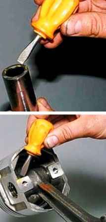
On the piston pin, the group is indicated by paint applied on its end face or inner surface
It must match the group indicated on the piston boss
On the connecting rod, the piston pin hole group is also marked with paint. It must either match or be adjacent to the finger of the group.
We check the correct selection of the connecting rod and piston pin in the following way
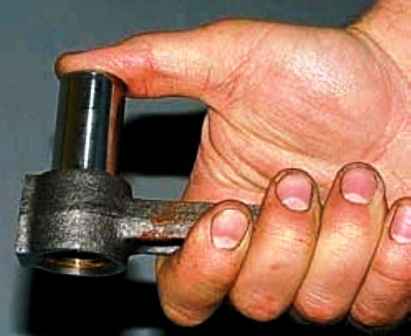
The finger lubricated with engine oil should move in the connecting rod head under the force of the thumb, but not fall out of the sleeve
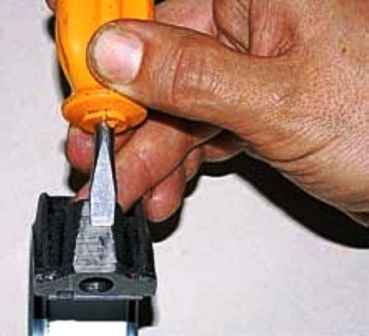
On the side surface of the lower head of the connecting rod and the cover there is a serial number of the cylinder in which it was installed
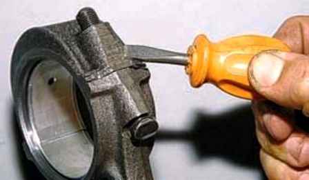
The numbers on the connecting rod cap and on the connecting rod itself must match and be on the same side
The connecting rods supplied as spare parts do not have such markings, therefore, before disassembling them, mark the connecting rods and caps in the same way as the factory ones so as not to turn over and confuse the caps during assembly
Heat the piston to a temperature of 60–80 °C. It is allowed to heat the piston in hot water

We insert the connecting rod head between the piston bosses and the hammer through the mandrel or with a tool we press in the piston pin lubricated with engine oil
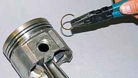
Install retaining rings on both sides
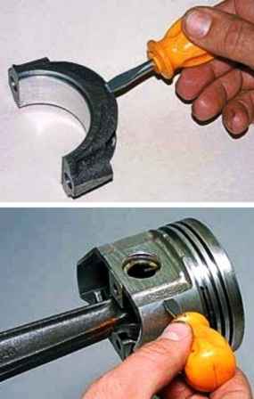
The protrusion on the connecting rod cap must be on the same side as the inscription "Front" on the piston
We carefully clean the seats of the sleeves from scale and corrosion
We replace the sealing copper washers of the cylinder liners with new ones
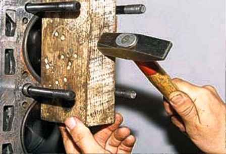
We press the sleeves with light hammer blows through a wooden block
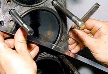
Using a probe, we check the protrusion of the sleeve above the plane of the block, which should be 0.02-0.10 mm
We select piston rings for cylinders
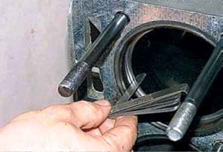
Alternately, we install the rings into the cylinder to a depth of 20–30 mm and measure the gaps with a probe
Compression rings should have a gap in the lock of 0.3–0.6 mm, oil scraper rings - 0.3–1.0 mm
If the pistons are not to be replaced, check the groove width with new piston rings
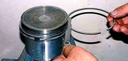
We check the gap at several points around the piston circumference
The value of the side clearance for compression rings should be 0.050-0.082 mm, for the assembled oil scraper ring 0.135-0.335 mm
In worn cylinders, you can install rings of the nearest repair size and, if necessary, file the ends to obtain a gap of 0.3 mm
We put the rings on the piston, starting with the oil scraper ring
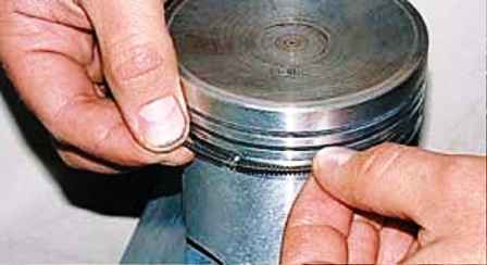
Having opened the lock of the oil scraper ring expander, we install it in the lower groove of the ring, after which we bring the ends of the expander together
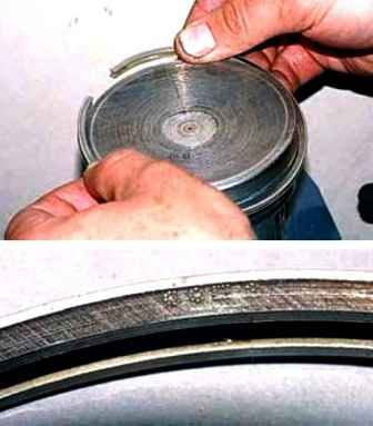
We put an oil scraper ring on the expander with an inscription to the piston bottom
Angle between expander and ring locks 45°
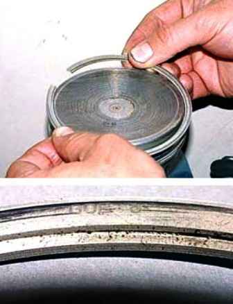
We install the lower compression ring with an inscription and a chamfer from the inside of the ring to the piston bottom
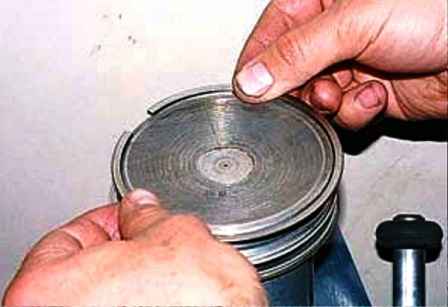
Installing the top compression ring


