Remove the starter as described in the previous article
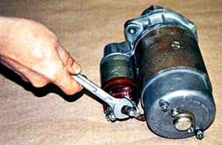
We unscrew the nut of the power wire to the traction relay with a 13 key and disconnect the wire tip
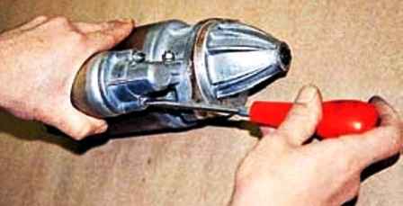
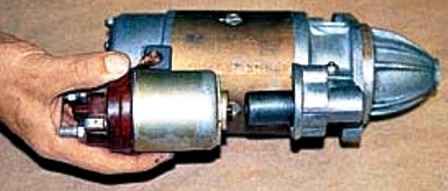
Using a screwdriver, unscrew the two screws securing the traction relay and remove the traction relay
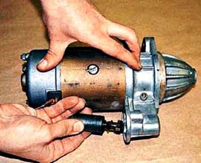
Remove the core with the stem
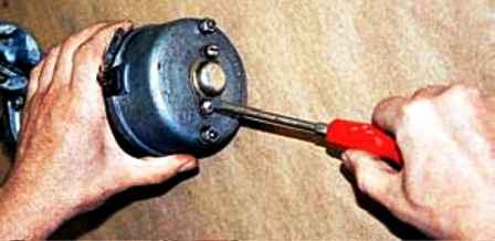
Unscrew the two screws securing the cover
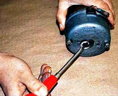
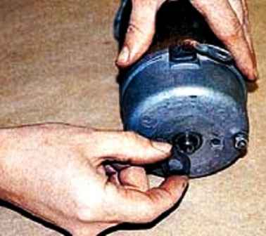
Pry off with a screwdriver, remove the retaining half ring and remove the washer
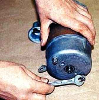
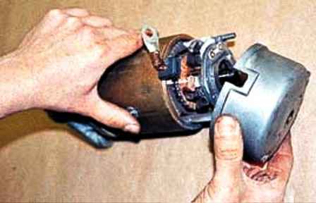
We unscrew the two fastening nuts with a 10 wrench and remove the back cover
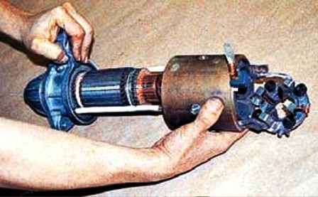
Moving the body off the studs
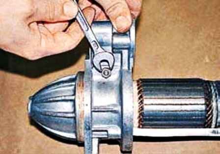
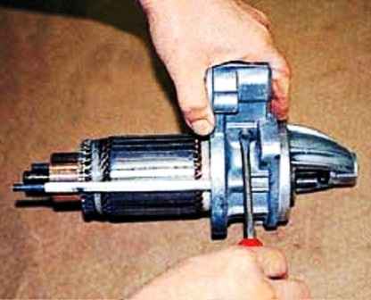
Unscrew the nut with a 10 key and unscrew the lever axis with a screwdriver
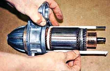
Remove the insulating tubes from the studs
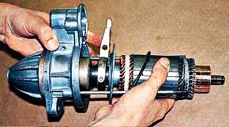
Remove the anchor from the front cover
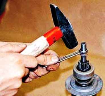
We rest the anchor axis on a wooden block, knock down the thrust sleeve through a 13 spanner wrench
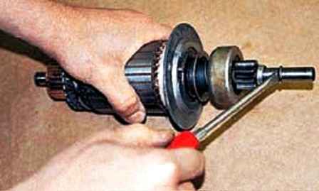
Pry off with a screwdriver and remove the spring ring
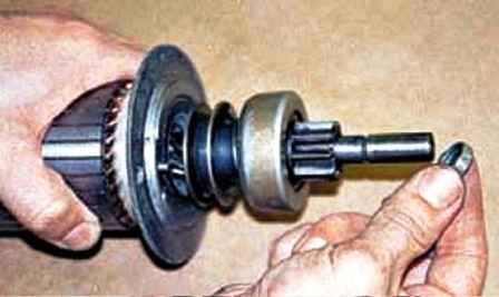
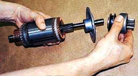
Remove the thrust sleeve and drive assembly (bendix) and intermediate support from the anchor
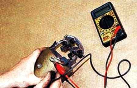
Using an ohmmeter, we check the absence of a short circuit of the stator windings to the case
On a healthy stator, the resistance will approach infinity
Defects in the armature windings are determined visually - the places of short circuits or breakdowns to ground turn black.
The collector must not show signs of burning and heavy wear.
Before assembly, we remove coal dust from the body and brush holder with compressed air.
We assemble the starter in the reverse order, lubricating the bushings and drive parts with a thin layer of FIOL-1 grease or engine oil.
We put the thrust sleeve on the shaft so that the conical groove faces the groove for the spring ring
Next, put the spring ring in place, press the sleeve onto it with a hammer blow through the “14” key or press it with sliding pliers
Having assembled the starter, we apply +12 V from the battery to the output of the traction relay winding, and “minus” to the case
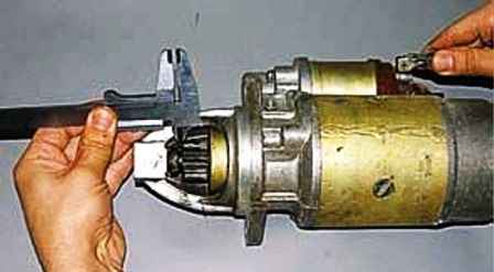
We measure the gap between the drive gear and the thrust sleeve with a vernier caliper
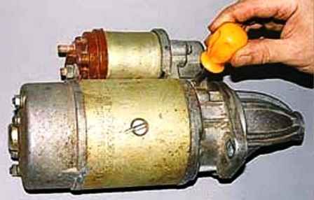
Rotate the lever axis with a screwdriver and set a gap of 3-5 mm
Tighten the lever axis nut and disconnect the wires
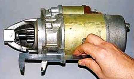
We measure the distance from the end of the drive gear to the mating plane of the starter, which should be no more than 34 mm
If necessary, repeat the adjustment
Replacing the starter relay
Disconnect the negative battery terminal
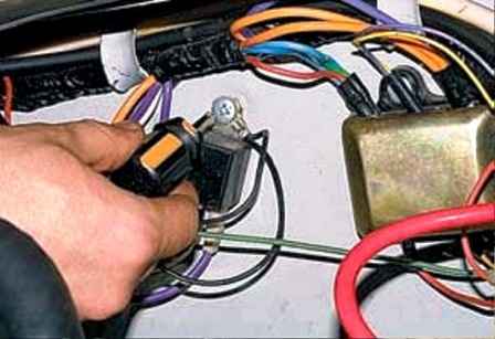
Under the hood, use a Phillips screwdriver to unscrew the screw that secures the relay to the partition of the engine compartment
The screw additionally secures the end of the ground wire
Mark the wires connected to the relay
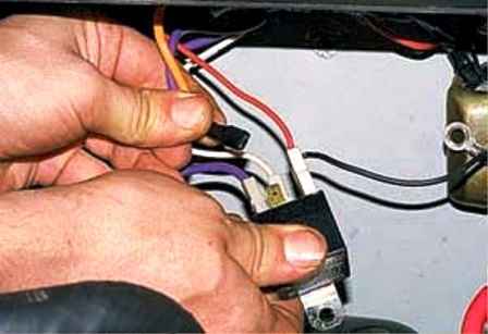
Remove the wire ends from the relay outputs
Connect the wires to the new relay and attach it to the body panel


