 ZH
 FR
 BE
 DE
 RU
 UK
 KK
 EN
 ES
Removal and installation of the UAZ engine lubrication system components
The oil system components are removed for replacement, as well as for repair and diagnostics.
We prepare the vehicle for the work and place it on an inspection pit or lift.
Required tools and materials
For the work, you will need: a set of open-end and ring spanners (12, 13, 17, 19, 22 mm), screwdrivers, pliers, a set of feeler gauges, an oil drain container. Materials: new sensors, oil cooler tap, gaskets, gasket-making sealant, engine oil for lubricating parts during assembly.
Removal and installation of the lubrication system sensors
We remove the front engine splash guard. To remove the oil pressure gauge sensor, we unscrew the wire terminal fixing screw of the sensor using a screwdriver.
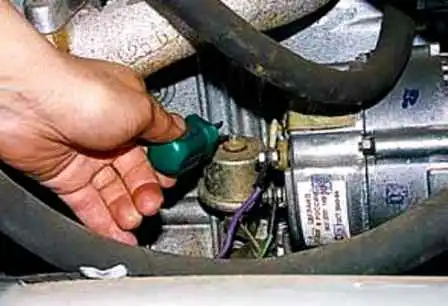
On the UMZ engine, this sensor is located under the alternator. Using a 17 mm spanner, we unscrew the sensor and remove it.
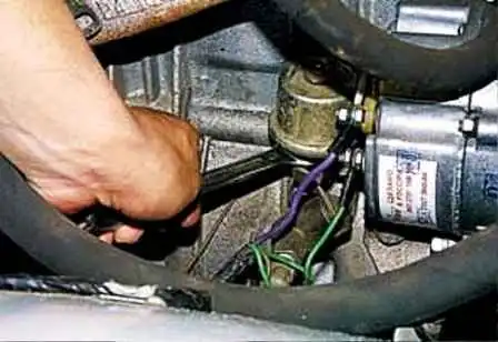
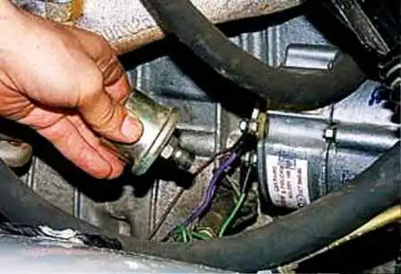
We install a new sensor, having previously applied sealant to its threaded part, and connect the wire terminal to it.
Removal of the low oil pressure warning light sensor
We disconnect the wire connector from the sensor.
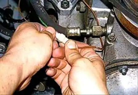
We unscrew the sensor with a 22 mm spanner, holding the stub with a 19 mm spanner, and remove it.
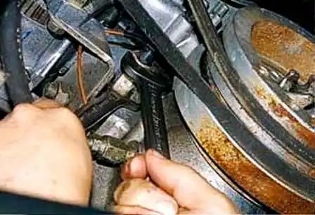
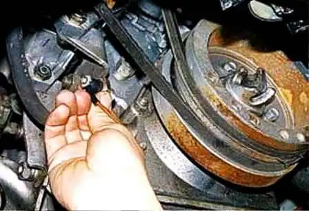
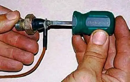
When installing a new sensor, it is imperative to apply sealant to its threaded part.
Replacement of the oil cooler tap
We disconnect the oil cooler hose, as described in the article "How to remove the oil cooler of the UAZ-3151, -31512, -31514, -31519 vehicle".
We unscrew the tap using a 19 mm spanner (in the picture, the alternator has been previously removed).
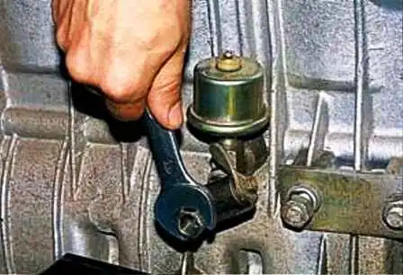
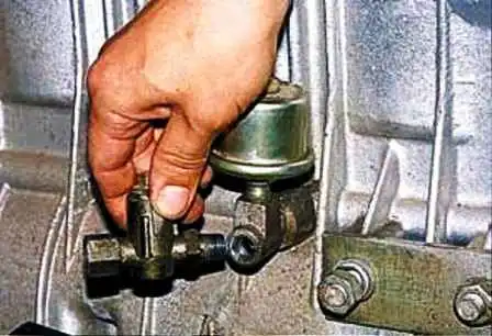
Before installing the new tap, we apply sealant to its threaded part. We install the tap in reverse order.
Removal and installation of the oil pump drive
We remove the ignition distributor. Using a 13 mm spanner, we unscrew the two nuts securing the drive housing to the cylinder block.
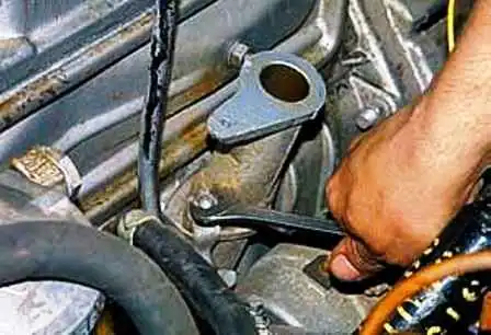
We extract the drive from the cylinder block. The drive is sealed with a gasket, which must be replaced before installation.
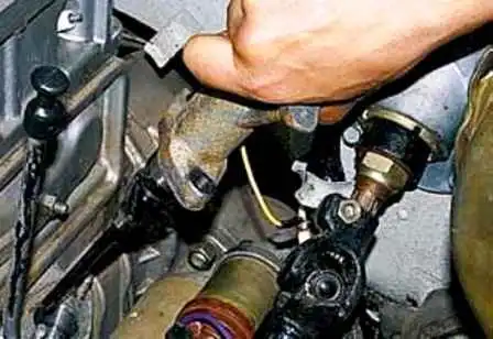
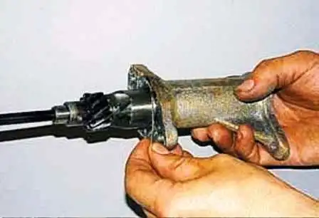
Installation of the oil pump drive
We set the piston of the first cylinder to TDC (top dead centre). We turn the drive shaft by 45°, as shown in the figure, and install the drive into the cylinder block.
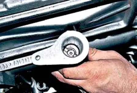
After the gears engage, the shaft will return to its initial position: its slot will become parallel to the longitudinal axis of the engine and, relative to the centre of the shaft, will be shifted outwards.
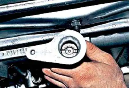
To check the correct connection of the oil pump shaft with the drive shaft, turn the crankshaft with the starter motor. There should be no extraneous knocking. We install the ignition distributor and adjust the ignition timing.
Removal and installation of the oil sump
We remove the engine splash guards. Using a 13 mm socket, we unscrew the twenty-one nuts securing the sump.
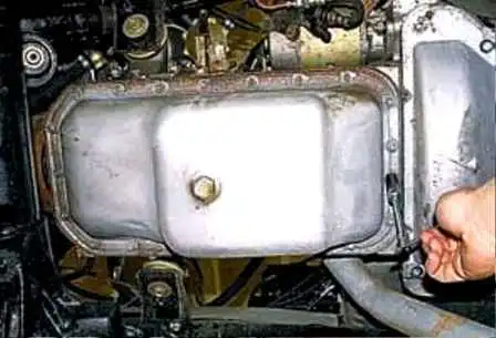
We remove the sump and peel off the old gasket.
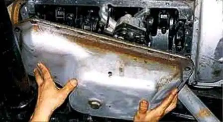
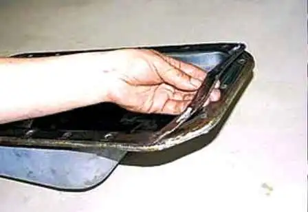
We install the sump in reverse order. For reliable sealing, we apply sealant to both sides of the new gasket.
Removal and disassembly of the oil pump
We remove the oil sump as described above. Using a 13 mm socket, we unscrew the two nuts securing the pump and remove the oil pump.
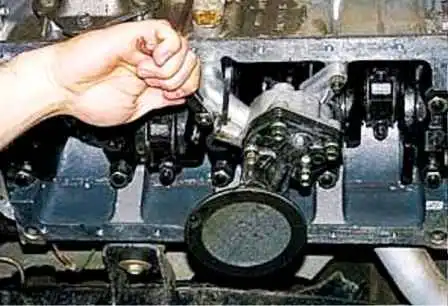
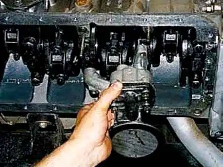
We unscrew the four bolts securing the oil strainer with a 12 mm spanner. We remove the oil strainer and the pump cover (a gasket is installed between them).
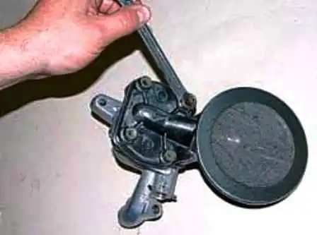
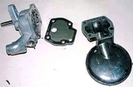
We extract the driving and driven gears.
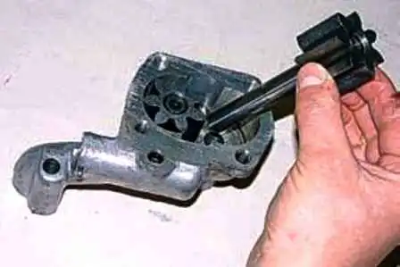
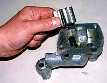
Using pliers, we remove the split pin and the adjusting washers, then we extract the spring and pull out the relief valve plunger.
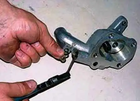
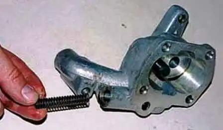
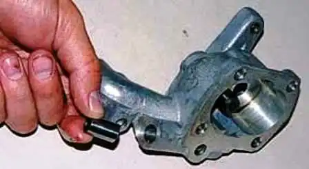
After this, we thoroughly wash all parts and inspect them for defects. Using a feeler gauge, we measure the clearance between the gear teeth and the pump body.
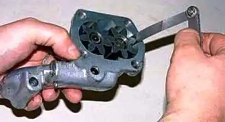
The clearance must not exceed 0.2 mm. We assemble the pump in reverse order, having previously lubricated the internal parts with engine oil. We install the pump onto the engine in reverse order.