
The system consists of a recirculation valve with a diaphragm, a thermal vacuum switch and two hoses
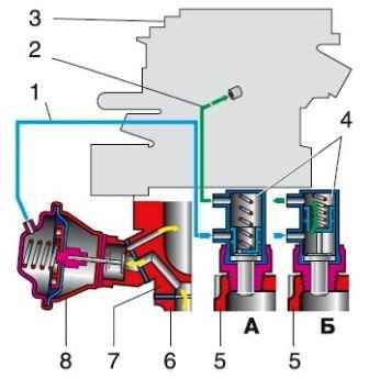
Scheme of the exhaust gas recirculation system: 1 - hose from the thermal vacuum switch to the recirculation valve; 2 - hose from the thermal vacuum switch to the carburetor; 3 - carburetor; 4 - thermal vacuum switch; 5 - cylinder head; 6 - exhaust manifold; 7 - inlet pipeline; 8 - recirculation valve; A - on a cold engine; B - on an engine warmed up to a coolant temperature of 40 ° C, at partial loads
The switch is connected by one hose to the carburetor over-throttle space, and when the engine is running, a vacuum is created in the hose.
Another hose goes to the switch from the recirculation valve.
When the engine warms up, the thermal vacuum switch valve opens and passes vacuum to the recirculation valve, opening it.
Part of the exhaust gases through the bypass hole is sucked into the intake manifold and burns out in the engine cylinders, which reduces the toxicity of the exhaust gases.
Removing the recirculation valve and thermal vacuum switch
Drain the liquid from the engine cooling system

Remove the two hoses from the thermal vacuum switch

Unscrew the switch from the cylinder head with a 27 spanner

Remove the hose from the recirculation valve fitting and unscrew the two nuts with a 13 wrench

Remove the recirculation valve from the exhaust manifold
A sealing gasket is installed between the valve and the manifold

Using an 8 key, unscrew the three bolts

Remove the valve from the body
We assemble and install the valve and switch in the reverse order

")
")
")
")
")
")
")
")