


In some vehicle trim levels a four-speed automatic transmission of the DPO model is fitted, which ensures the selection of the optimum gearshift mode for virtually any driving style and road conditions.
The automatic transmission is arranged according to the traditional planetary layout with friction braking and is connected to the engine crankshaft through a torque converter.
The electronic control system of the automatic transmission constantly monitors the vehicle speed and engine load, eliminates driver errors by not allowing a higher gear to be engaged at low speed in order to avoid overloading the engine, or a lower gear at too high a speed, which excludes the possibility of exceeding the maximum permissible crankshaft speed of the engine.
When the vehicle speed decreases, the gears automatically shift to lower gears without driver involvement.
At the moment of complete standstill of the vehicle, 1st gear is engaged automatically.
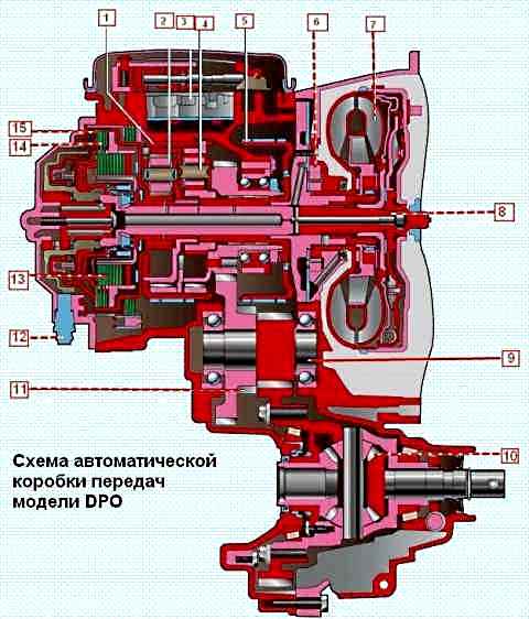
The automatic transmission consists of a torque converter, a pump, a planetary gearset, multi-plate clutches, multi-plate brakes and a valve block.
The torque converter performs the functions of a clutch and serves to smoothly connect the engine to the gearbox mechanism and to increase torque at the start of vehicle movement.
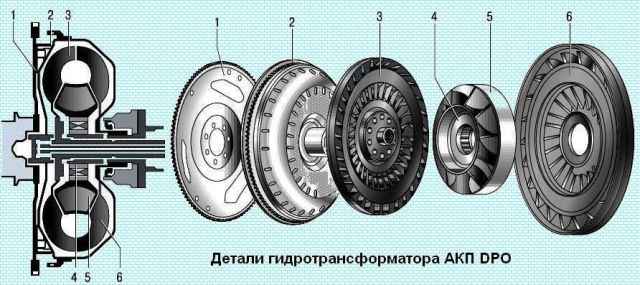
The torque converter housing is connected to the engine crankshaft through the drive plate and rotates constantly when the engine is running.
The internal cavity of the torque converter is filled with working fluid for automatic transmissions.
The engine rotates the torque converter and drives the pump wheel, which creates flows of working fluid towards the turbine wheel.
The turbine wheel begins to rotate due to the flows of working fluid created by the pump wheel.
With a large difference in rotational speeds of the turbine wheel and pump wheel, the reactor changes the direction of the fluid flow, increasing torque.
As the speed difference decreases, it becomes unnecessary and is therefore mounted on a one-way clutch.
The pump, installed in the front part of the gearbox housing, creates pressure and supplies working fluid to all systems in the gearbox.
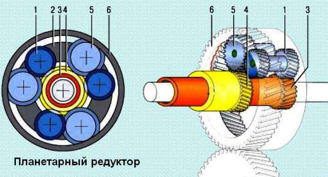
The planetary gearset is a toothed gearing with external and internal gear meshes, which provides various ways of connecting its elements to obtain different gear ratios.
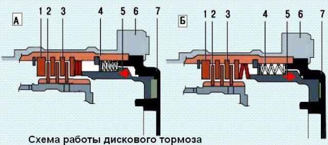
The operating principle of multi-plate clutches and disc brakes is very similar, the difference being that the multi-plate clutch connects the gearbox elements to each other, while the disc brake connects them to the gearbox housing.
The working fluid supplied to the clutch actuates the piston and the friction discs are compressed.
The elements locked by the clutch begin to rotate as a single unit.
When the disc brakes are disengaged, the working fluid stops being supplied to the clutch and the piston, under the action of the return spring, returns to its initial position.
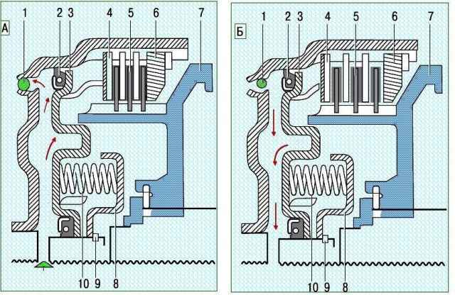
The design feature of the multi-plate clutch is that it is in constant rotation and, under the action of the centrifugal force acting on the working fluid, pressure is created which prevents the clutch from unlocking.
Additionally, a ball valve is fitted in the clutch.
It is located as close as possible to the edge from the centre of the clutch.
When the pressure of the working fluid in the chamber of the multi-plate clutch increases, the ball valve closes the drain hole, and when the pressure in the chamber decreases, the ball valve, under the action of the centrifugal force, opens the drain hole and the clutch unlocks.
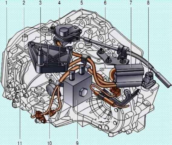
The automatic transmission control drive is cable-operated, designed on the same principle as the manual gearbox control drive, but differs from it in the number and design of the parts.
The automatic transmission selector is installed in the same place on the floor tunnel as the manual gearbox control lever, and is connected to the control unit on the gearbox by a cable.
The differential of the automatic transmission is completely analogous in design to the differential of the manual gearbox.
In the differential housing two sealed holes for the output shafts are provided, which allows the gearbox to be removed without draining the working fluid.
Dismantling of the automatic transmission is covered in the article – «Dismantling of the DPO automatic transmission».
Repair of the hydraulic valve block of the automatic transmission is covered in the article – «Operating principle and repair of the DPO (AL4) automatic transmission hydraulic valve block».


