The efficiency of starting and running the engine largely depends on the quality and correct fuel injection.
Checking for air in the fuel system
After replacing fuel pipes, fuel filters, injection pump and injectors, air remains in the fuel system.
This causes poor starting, uneven idling, misfiring, reduced power, and uneven fuel delivery.
A few air bubbles found in the fuel line during inspection are normal.
A lot of small bubbles (foam) indicate the presence of air leakage into the system, high resistance at the inlet, which causes cavitation, or insufficient filling of the fuel system.
If the resistance at the fuel inlet is correct, identify the source of air entry among the following:
- - intake fuel lines;
- - fuel lines for attachments;
- - inlet fittings of fuel filters;
- - fuel tank intake pipes.
Disconnect the fuel supply line of the fuel pump.
Install the gauge adapter (#4918462) between the ECU cooler plate and the fuel pump.
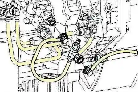
Start the engine.
Raise and lower the idle speed several times to bleed air.
Let the engine idle while watching the flow of fuel from the transparent hose.
If air continues to bubble in the hose for a few minutes, air is getting into the fuel system.
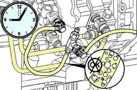
Check the fuel system for damaged fuel lines and loose connections.
Replace damaged pipes and tighten loose connections.
Air removal
Models with manual booster pump
Note: It is not necessary to bleed the high pressure fuel system before starting the engine.
The system will fill with fuel when cranking the starter.
If there is no fuel in the filter and lines, perform 120 strokes of the manual priming pump before starting the engine.
If there is fuel in the filter and lines, perform 40 strokes of the manual priming pump before starting the engine.
Start the engine and check for leaks.
Checking for blockage in the fuel inlet line
Remove the nipple bolt from the fuel pump inlet.
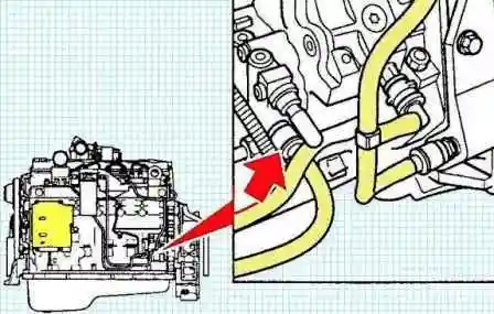
Measurement of resistance at the fuel inlet requires the use of the pressure gauge installation kit (p/n 4918462).
Install the M12 (male) x M12 (female) adapter included in the pressure gauge fitting kit onto the fuel inlet fitting.
Install the bolt provided in the Gauge Installer Kit to the fuel inlet and adapter.
Install a vacuum gauge with a measurement range of at least 0 - 508 mmHg. Art. on the pressure gauge adapter.
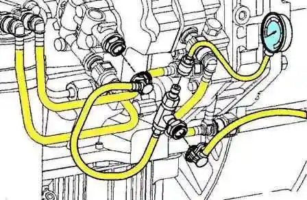
Set the idle speed to high and measure the resistance at the fuel inlet.
Permissible fuel inlet resistance at high idle 50.8 kPa
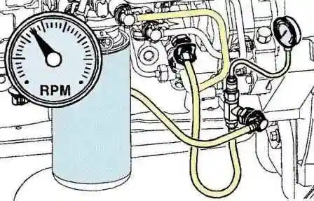
If the resistance at the fuel inlet is high, check that the attachment lines from the tank are properly sized for kinks and blockages.
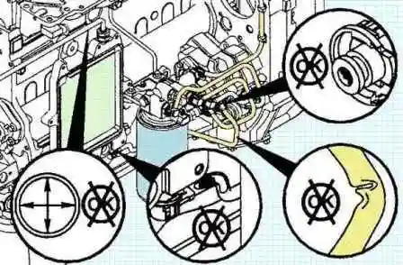
Check for clogged coarse and fine filters, and for faulty non-return valves.
Check the resistance of the fuel filter.
Check the absence of fuel x tanks of attachments of debris (plastic bags, paper, etc.), which can periodically block intake pipes.
Check attachment fuel lines for internal damage, such as pipe wall lining defects, which can cut off fuel flow from time to time.
If the problem occurs intermittently and the cause cannot be determined during engine service, install the Fleetguard Fuel Filter Indicator (P/N 3892576) in the connector between the fuel lines and the engine.
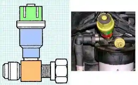
The indicator will show the maximum differential pressure in mmHg. st.
When a problem occurs, the clogged fuel filter indicator will show that the problem is due to a faulty equipment.
Removing and installing fuel return line
Mark the position of all P-locks and fuel return lines so that they can be reinstalled in the positions they were removed from.
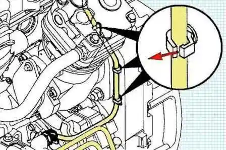
Remove all capscrews from the P-shaped retainers securing the fuel return lines.
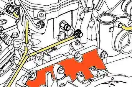
Disconnect the fuel return line connector from the fuel return fitting from the injectors on the back of the cylinder head.
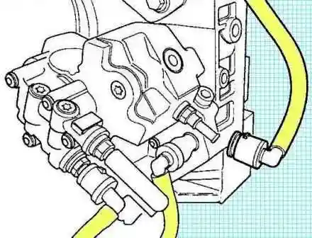
Disconnect the fuel return line from the injection pump.
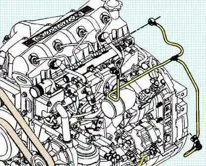
Disconnect the fuel return line from the return manifold.
Installation
Lay the fuel return line in accordance with the marks made during removal.
Connect the fuel return line connector to the injector fuel return fitting on the back of the cylinder head.
Connect the fuel return lines to the manifold.
Connect the fuel return line to the injection pump.
Checking the fuel supply
Clean all connections before disassembly.
Ingress of dirt can cause damage to the fuel system.
Disconnect the high pressure fuel pipe from the injection pump to the fuel accumulator.
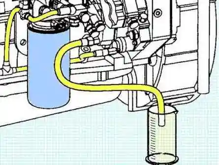
Connect a clean hose to the injection pump outlet.
Put the other end of the hose into a measuring container.
Engage the starter for 30 seconds and measure the fuel supply of the injection pump.
Rated feed:
- - at 125 rpm 45 ml
- - at 150 rpm 53 ml
If the fuel supply is different from the specified, perform the following checks:
- make sure there is no air in the fuel system:
make sure there is no blockage in the fuel inlet line;
- check the fuel control valve.
If the fuel supply is less than the minimum value after replacing the injection control valve, replace the injection pump.
Reconnect the supply control valve connector and clear any DTCs using a scanner.
Checking fuel drain
Warning: The fuel injection pump outlet pipes contain fuel at very high pressure.
To avoid personal injury or property damage, do not loosen any connections while the engine is running.
If the engine does not start, check the fuel flow through the fuel return line.
High fuel flow through the drain line may cause a malfunction of the drain line bypass valve or high pressure pump.
Disconnect the fuel drain quick coupling from the injection pump.
To reduce the risk of fuel leakage from the combined fuel accumulator and injector drain line, plug the flexible fuel drain line with a fuel line plug (P/N 24918464).
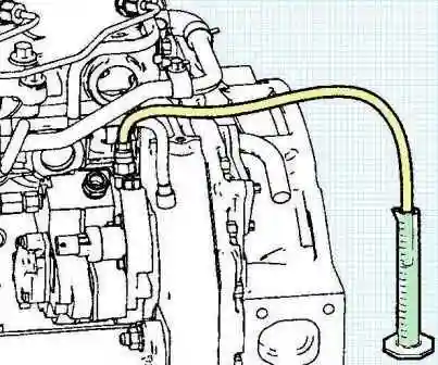
Place the drain hose with quick coupling (No. 49184Z4) on the drain fitting of the fuel pump.
Place the end of the fuel drain hose in a measuring container.
Start the engine and let it idle.
Measure the fuel consumption within 30 seconds after it starts to flow into the measuring container.
Maximum flow through fuel return line:
- at 800 rpm 317 ml
If the flow rate is higher than the maximum value, check the fuel system for air and make sure there is no blockage in the fuel intake line.
If the results of these checks are satisfactory, replace the injection pump.


