


We check and adjust the valve clearances during cylinder head repair, as well as when a sharp knocking noise appears in the upper part of the engine.
We carry out the check and adjustment with the engine coolant temperature below 60 °C.
- Remove the cylinder head cover.
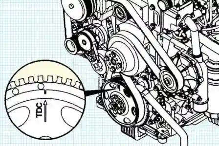
- Turn the crankshaft and set the No. 1 cylinder piston to TDC of the compression stroke.
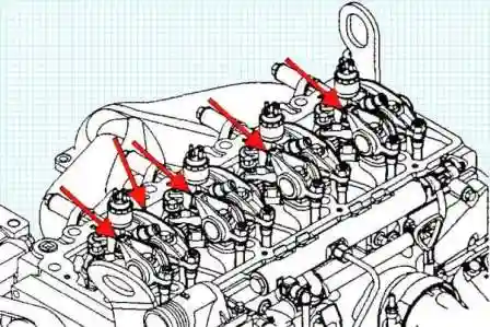
- Check the clearance in the valve train:
- first inlet;
- first exhaust;
- second inlet;
- third exhaust.
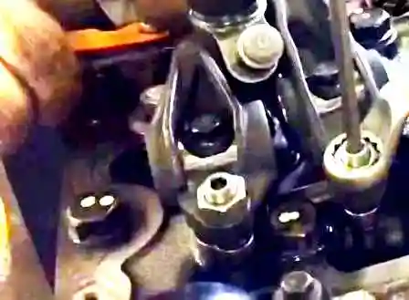
With a correctly adjusted clearance, the feeler gauge passes with slight resistance between the rocker bridge and the rocker seat.
Nominal clearance:
- inlet valve: 0.280–0.381 mm;
- exhaust valve: 0.530–0.630 mm.
If the clearance differs from the nominal value, loosen the locknut and adjust it with the adjusting screw.
Tighten the locknut and check the clearance again. Nominal clearance (during adjustment):
- inlet valve: 0.33 mm;
- exhaust valve: 0.58 mm.
Locknut tightening torque: 24 N·m.
- Turn the crankshaft through 360°.
- Measure the clearances in the valve train of the remaining valves:
- second exhaust;
- third inlet;
- fourth exhaust;
- fourth inlet.
- Adjust the clearances if necessary.
- Install all parts in the reverse order.


