The Cummins ISF engine control unit has a two-piece connector.
The "A" block is connected to the vehicle's wiring harness. Its composition can vary widely depending on the configuration of the car
Through this block, among other things, the control unit receives power and is connected to the vehicle ground.
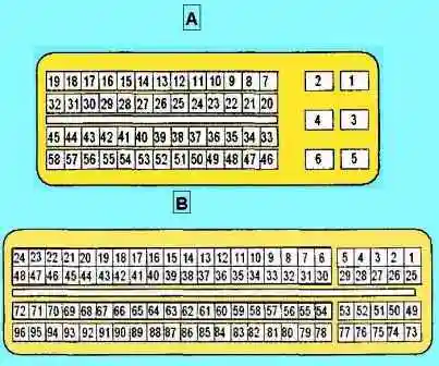
The block "B" combines the engine wiring: sensors and actuators.
Its elemental composition depends on the toxicity standards that the engine in question complies with.
Crankshaft position sensor
The crankshaft position sensor is installed in the area of the crankshaft pulley.
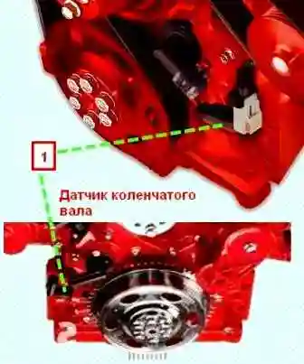
The principle of operation of the crankshaft position sensor is based on the Hall effect.
The sensor determines the position of the crankshaft, and converts this data into signals (rectangular pulses).
Based on these signals, the electronic engine control unit determines the engine crankshaft speed and corrects the moment when the nozzle opens, as well as the duration of its open state and the fuel injection advance angle.
The sensor has three wires: power, ground and signal wire.
The power supply of the sensor is stabilized, it is approximately 5 V and is provided by the engine control unit (terminal B13).
The ground contact is also connected to the control unit (terminal B14).
The sensor signal is sent to the B38 terminal of the control unit and is a rectangular pulse with a low level of approximately 0 V and a high level of approximately 5 V.
The main sensor malfunctions lie in three areas:
Failure of the sensor itself
A malfunction of the Hall effect sensors manifests itself mainly after the engine has warmed up - the electronics built into the sensor fail due to heating.
Pulse gaps occur.
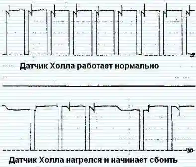
Wiring fault
It manifests itself in the form of a complete or partial absence of a sensor signal.
It is diagnosed by checking the voltage at the sensor contacts with the ignition on and the connectors on. And also the continuity of the wiring from the sensor to the control unit with the connectors removed.
Failure of the sensor rotor (drive wheel)
It should be noted that the repair of the rotor teeth in case of damage is unacceptable - the rotor must be replaced.
Welding changes the magnetic properties of the material and the sensor signal is likely to fail when passing by the repaired tooth.
The absence of movement of the tachometer needle in the event of unsuccessful attempts to start the engine may serve as an indicator of a possible malfunction of the crankshaft position sensor.
Camshaft position sensor
The camshaft position sensor is located on the cylinder head and detects the moment the piston of cylinder No. 1 arrives at top dead center on the compression stroke.
Based on the signal from the sensor, the electronic engine control unit determines the sequence of fuel injection for individual cylinders.
The principle of operation of the camshaft position sensor is based on the Hall effect.
The sensor has three wires: power, ground and signal wire.
The power supply of the sensor is stabilized, is approximately 5 V and is provided by the engine control unit (terminal B87).
The ground contact is also connected to the control unit (terminal B63).
The sensor signal is sent to contact B62 of the control unit and is a rectangular pulse with a low level of approximately 0 V and a high level of approximately 5 V.
The main sensor malfunctions lie in three areas:
1) Malfunction of the sensor itself.
A malfunction of the Hall effect sensors manifests itself mainly after the engine has warmed up - the electronics built into the sensor fail due to heating.
Pulse gaps occur.
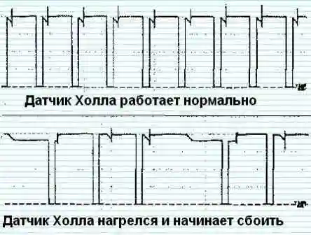
2) Faulty wiring, including connectors. It manifests itself in the form of a complete or partial absence of a sensor signal.
Diagnosed by checking the voltage on the contacts sensor with the ignition on and the connectors plugged in. And also the continuity of the wiring from the sensor to the control unit with the connectors removed.
3) Malfunction of the sensor rotor (drive wheel).
Boost pressure sensor and air temperature sensor assembly
The boost pressure sensor is mounted on the intake manifold and is a piezoresistive type sensor.
The sensor detects the boost pressure generated by the turbocharger directly in the intake manifold, producing an output signal to the control unit.
The charge air temperature sensor is integrated into the boost pressure sensor.
The sensor has four wires: power, ground, boost pressure sensor signal wire and charge air temperature sensor signal wire.
The power supply of the sensor is stabilized, is approximately 5 V and is provided by the engine control unit (terminal B89). The ground contact is also connected to the control unit (terminal B65).
The signal from the boost pressure sensor is sent to terminal B70 of the control unit and represents a voltage that increases with increasing pressure.
The charge air temperature sensor signal is sent to contact B23 of the control unit.
Fuel manifold pressure sensor
The fuel pressure sensor is mounted on the fuel accumulator (fuel manifold) and measures instantaneous fuel pressure values in the accumulator with adequate accuracy and speed.
Fuel enters the sensor through a hole in the accumulator and a channel in the sensor housing, closed at the end by a diaphragm, so the pressurized fuel acts on the diaphragm.
The sensing element of the sensor, in turn, converts the pressure into an electrical signal.
This signal is sent to the ECM.
Based on the signal from the fuel pressure sensor and depending on the signals from other components of the fuel system, the electronic engine control unit makes the necessary adjustments to the operation of the fuel system (the necessary fuel pressure is created in the accumulator by controlling the executive element of the injection pump).
The sensor has three wires: power, ground and signal wire.
The power supply of the sensor is stabilized, is approximately 5 Volts and is provided by the engine control unit (terminal B92).
The ground contact is also connected to the control unit (terminal B68).
The sensor signal is sent to contact B69 of the control unit and represents a voltage that increases with increasing pressure.
Coolant temperature sensor
The coolant temperature sensor is installed in the thermostat housing.
It detects the temperature of the engine coolant and transmits a signal to the electronic engine control unit.
The sensor is a thermistor.
Sensor resistance decreases with increasing coolant temperature.
The electronic engine control unit, based on the voltage of the sensor signal, estimates the temperature of the coolant and makes the necessary adjustments to the operation of the fuel system.
The sensor has two wires: ground (terminal B43 of the control unit) and a signal wire, which is also a power supply (terminal B46 of the control unit).
With the ignition on, a stabilized power supply of approximately 5 V should be present on pin 2 of the disconnected sensor connector.
Accelerator pedal position sensor
The accelerator pedal position sensor is needed to determine how much the driver has pressed the accelerator pedal.
The sensor consists of two potentiometers (variable resistors) with independent circuits (power, signal and ground).
Thus, the sensor consists of two channels - 1 and 2.
When you press the accelerator pedal, the resistance of the sensor resistors smoothly change in proportion to the degree of pressing the pedal.
The signals from the accelerator pedal position sensor coming to the electronic engine control unit are compared with the programmed characteristic curves (the signals from channel 1 and 2 are also compared with each other, this is necessary to control the correctness of the readings).
The electronic unit, in turn, generates output control signals, on the basis of which the operation of the fuel system is controlled (for example, it determines the required fuel supply).
Emergency oil pressure sensor
The emergency oil pressure sensor is a relay (switching) sensor, the contacts of which are closed when the oil pressure in the engine lubrication system drops below a certain level.
The sensor signal enters the control unit at pin 37V - the sensor closes this circuit to ground.
When a signal is received from this sensor while the engine is running (a signal from the crankshaft position sensor is received), the engine control unit commands the “STOP” malfunction indicator to turn on on the instrument panel.
Depending on the implementation of the data exchange system between instrument cluster and engine control unit, this command can be transmitted both via a separate circuit (terminal A49) and via the CAN data bus (terminals 14A and 15A).
Atmospheric pressure sensor
Atmospheric pressure sensor detects the current atmospheric pressure and sends a signal to the engine control unit.
This sensor is necessary for the correct operation of the engine at different altitudes.
The sensor has three wires: power, ground and signal wire.
The power supply of the sensor is stabilized, is approximately 5 V and is provided by the engine control unit (terminal B88).
The ground contact is also connected to the control unit (terminal B64).
The sensor signal is sent to terminal B72 of the control unit and represents a voltage that changes with pressure.
Actuators
High pressure fuel pump (high pressure fuel pump)
There is an electromagnetic fuel pressure regulator on the injection pump.
It maintains the operating pressure of the fuel in the accumulator depending on the load on the engine.
If it is necessary to increase the fuel pressure in the accumulator, the solenoid regulator valve closes on a signal from the electronic engine control unit, shutting off the high pressure stage from the low pressure line (fuel return).
If it is necessary to reduce the fuel pressure in the accumulator, the solenoid regulator valve, on the contrary, opens upon a signal from the electronic engine control unit, bypassing part of the fuel into the return line and thereby reducing the fuel pressure in the accumulator.
Injectors
The injectors inject fuel into the engine cylinders according to a signal from the electronic engine control unit.
In a common rail common rail fuel system, injectors with an electromagnetic drive are installed.
Turbocharger geometry change drive
Some modifications of the engine have a variable geometry turbocharger.
The drive of the geometry change system is installed on the turbocharger and controls the geometry change system (blade position) of the turbocharger.
The electronic engine control unit, receiving data from the crankshaft position sensor, coolant temperature sensor, charge air temperature sensor, boost pressure sensor and atmospheric pressure sensor, which determine the load on the engine and its operating conditions, calculates the optimal position of the blades and supplies signal to the drive motor.
Thus, the performance of the compressor apparatus of the turbocharger is regulated.
CAN data bus
The CAN (Controller Area Network) data bus is a high-speed serial data link developed by Bosch.
High noise immunity and error protection.
Used to reduce the number of wires when communicating in a car.
Each of the control units operating on this bus transmits and receives data selectively.
The bus is made according to a two-wire scheme: Can-High (H) and CAN-Low (L) channel.
Wires are twisted into a twisted pair to improve noise immunity of the bus.
The maximum length of untwisted wires should not exceed 40 mm, to ensure the necessary potential difference between H and L. channels, as well as to prevent errors in messages, possible when signals are reflected, inside the blocks, at the ends of the bus, parallel to the CAN-pins busbars have built-in resistors, usually 120 ohm.
These resistors also help to determine the health of the bus wiring on its different branches: by measuring the resistance on the corresponding contacts of the removed connectors of the control units operating on the CAN bus, you should usually get about 120 or 60 ohms (one 120 ohm resistor or their parallel connection).
Depending on which block connector is removed (variations are possible).
Depending on the implementation of the system, these resistors can be installed inside the control units, inside the intermediate CAN bus connectors, or inside special CAN bus terminators.
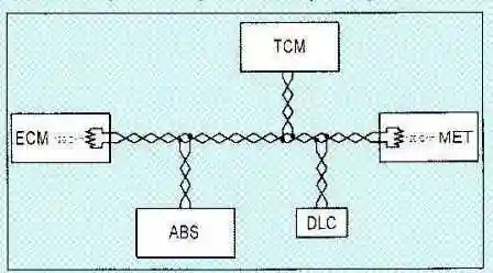
An example of building a CAN data bus on a car (various options are possible)
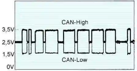
The load of the information bus depends on the number of blocks on it and on the amount of transmitted information.
The signals on both channels are always symmetrical to each other and are in antiphase.
At rest, both bus channels (High and Low) should see about 2.5 V (corresponding to a logic “1”).
CAN-Low channel signal (1) toggles between its 2.5V high level (logic '1') and 1.5V low level (logic '0').
The CAN-High (H) channel signal toggles between its 2.5V low level (logic “1”) and its 3.5V high level (logic “0”).
Thus, when the bus is switched to logic “0”, the potential difference between the channels is 2 V.
Possible malfunctions of the CAN bus lie in three areas:
- 1) Wiring/connector failure (open, short, short to ground or power).
- 2) Malfunctions of control units operating on the bus.
- 3) Superimposition of pickups on the CAN bus wiring (wrong wiring routing, wiring is not twisted into a twisted pair).
Emission control system
Modern engines must meet increasingly stringent emissions requirements.
In order for the engine to meet more stringent environmental requirements, its design is optimized, the control system and fuel equipment are improved, and additional subsystems for reducing exhaust gas toxicity are installed.
In addition, the correct fuel must be used.
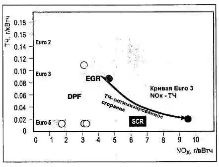
The following figure shows an approximate graph of the effect of the introduction of emission control subsystems on the corresponding emission parameters NOx oxides of nitrogen. PM - particulate matter incl. soot.
Exhaust gas recirculation (EGR) subsystem
The exhaust gas recirculation (EGR) subsystem is installed on some engine models to achieve Euro-3 toxicity standards, and together with fuel correction and Euro-4 standards.
It may not be available on Euro 3 engine models.
The EGR subsystem reduces emissions of nitrogen oxides (NOx) into the atmosphere.
Molecular nitrogen is present in the air and under normal conditions it is inert and does not react with oxygen, which is also present in the air.
But, getting into the combustion chamber of the engine, under the influence of high temperatures, nitrogen is oxidized, resulting in the formation of toxic nitrogen oxides.
And the higher the temperature, the more nitrogen oxides appear.
The EGR system directs part of the exhaust gases from the engine exhaust manifold through the intake manifold back to the combustion chambers, thereby lowering the combustion temperature of the air-fuel mixture, thereby reducing the formation of nitrogen oxides.
Composition of the EGR subsystem
There are several versions of the EGR subsystem. on Cummins ISF engines, depending on which its composition varies.
On ISF3.8 engines, the EGR subsystem includes: an EGR valve assembly, an EGR cooler and elements of an electronic control system.
The EGR valve has an electric drive that, at the command of the control unit, opens and closes the recirculation channel to the required amount.
The amount of recirculated gases is determined by the mass air flow sensor: a decrease in air flow lets the control unit know that exhaust gases are entering the engine.
A throttle servo is mounted on the intake manifold and is required to control the throttle position.
The servo consists of a DC motor and a throttle position sensor.
A throttle valve servo in the intake system of a diesel engine serves to increase the degree of exhaust gas recirculation by reducing the increased pressure in the intake manifold (this is achieved by closing the throttle valve), as a result of which exhaust gases are sucked into the intake.
Throttle control is carried out only at low speeds.
EGR Disadvantages
During operation, the soot contained in the exhaust gases clogs the recirculation channels and the EGR valve.
Thus, sooner or later the movement of the valve is blocked, and it ceases to perform its functions.
Normally, valve blocking occurs when it is partially open, so that recirculated gases are always fed into the intake tract, even when this should not happen.
This leads to a violation of the composition of the air-fuel mixture, and as a result, the loss of available power, an increase in exhaust smoke pa.
This problem is not always solved by flushing the valve: it may fail and need to be replaced.
Exhaust particulate matter also clogs the intake manifold, intake valves.
Clogging can be so severe that the car can simply stand up - air stops flowing into the engine.
Flushing the intake manifold solves this problem. In addition, due to EGR, engine oil loses its properties faster.
In addition, EGR worsens the fuel efficiency of a diesel engine, leading to a decrease in its thermal efficiency.
As you can see, this subsystem causes some harm to the engine, so many car owners remove its elements: all gas recirculation pipes, a recirculation valve, a gas cooler (a heat exchanger in which the heat of recirculated exhaust gases is transferred to the engine cooling system) are removed), plugs are installed instead all nozzles.
But this is not enough: if only the physical removal of the EGR subsystem is limited, then the control unit that controls its operation will detect a malfunction and inform the driver about it by turning on the indicator on the instrument panel.
Therefore, an additional flashing of the engine control unit is required (replacement of the control program - chip tuning), as a result of which the unit will no longer control the EGR elements, and the working control cards will be replaced with cards that comply with Euro-3 standards.
Particulate filter (DPF)
Soot from the exhaust gases of internal combustion engines, acting like activated carbon, collects harmful substances and is a carcinogen, so its inhalation is highly undesirable.
To reduce the amount of soot and other particulate matter in the exhaust gases of a car, the diesel particulate filter (Diesel Particulare Filter, DPF) is designed.
Its function is to capture the particulate matter from the exhaust gases and burn them periodically (DPF regeneration).
The total surface area of the filter element is close to the area of two football fields.
As you can see from the graph above, the DPF works in conjunction with the EGR: EGR reduces nitrogen oxides, but increases the amount of particulate matter in the exhaust gases, which in turn is solved by the DPF.
Composition of the DPF subsystem
The DPF subsystem consists of a diesel particulate filter and a differential pressure sensor in the particulate filter.
In this composition, this system is installed, for example, on Next Bus buses.
A differential pressure sensor in the particulate filter is required to control the filling of the filter.
Its readings allow the control unit to determine the moment when regeneration is required.
Regeneration of the particulate filter is carried out by heating it to a temperature of about 700 degrees, as a result of which the solid particles that have settled in its channels completely burn out, forming gaseous carbon oxides.
Disadvantages of DPF
Mistakes in vehicle operation, poor fuel quality, unsuitable lubricants, use of unsuitable fuel and oil additives, frequent short distance driving and city driving often lead to fatal diesel particulate filter failures.
It becomes impossible to regenerate.
Faced with this problem, the car owner, as in the case of a catalyst, has two ways to solve it: replacing it with a new one or removing the soot.
The cost of a new diesel particulate filter is high and often removing it is the only way to get your car back up and running.
And in this case, a flashing of the engine control unit will also be required to programmatically disable the particulate filter.
Selective Catalytic Reduction Converter (SCR)
This subsystem is designed to reduce toxic nitrogen oxides NOx (NO, NO2) in exhaust gases
The presence of this subsystem eliminates the need to use EGR to achieve Euro-4 standards, and its use in conjunction with other systems to reduce toxicity makes it possible to achieve Euro-5 and Euro-6 standards.
As you can see from the graph, when using this subsystem, the engine operates at modes optimized for reducing particulate matter in exhaust gases (PM-optimized combustion), and in this case, increasing the content of NOx in the exhaust gases is solved by the SCR subsystem.
The principle of operation of the SCR system is to treat exhaust gases (EG) with an aqueous solution of urea in a reductive catalytic converter.
Nitrogen oxides NOx (NO, NO2) contained in the exhaust gases are converted into nitrogen N2 after a chemical reaction with the AdBlue reducing agent in the catalytic converter and water H2O.
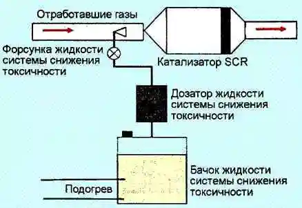
Emission control fluid (urea)
The aqueous urea solution used is known under the brand name AdBlue
AdBlue reagent, produced using a special technology from highly purified urea and demineralized water.
The proportion of urea in AdBlue is 32.5%.
At this concentration, the reagent has the lowest freezing point of -11°C.
Any deviation from the dacha concentration leads to an increase in the freezing point.
Heating of the urea supply system can be carried out both by independent heating elements and from the vehicle cooling system (in this case, the tank heating valve is used).
Average reagent consumption varies depending on the engine model and should average about 4% of diesel fuel consumption for Euro 4 engines.
The shelf life of the reagent is 1 year.
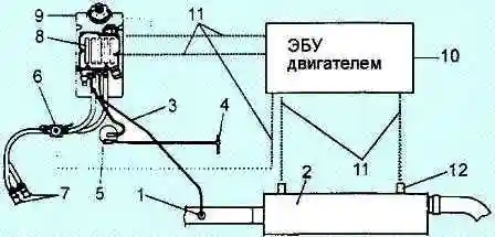
Precautions
The reagent is not flammable and is classified as safe according to the EC67/548/EEC directive.
Introduction of the substance into the body in small quantities does not pose a danger.
If AdBlue gets into the digestive system.
It is necessary to rinse the mouth and drink plenty of water.
If the feeling of malaise and discomfort persists, you should consult a doctor.
Prolonged contact or immersion of heat parts in a tank with a substance may cause skin burns.
If contact with the substance is possible, latex gloves should be used.
Although the product is not classified as an irritant chemical, direct contact with the eyes may cause short-term discomfort characterized by tearing or conjunctival redness.
In case of direct contact with the solution in the eyes, rinse them immediately with plenty of water and consult a doctor.
Reagent spills should be cleaned up carefully to prevent injury as the spill surface becomes slippery.
You should avoid getting liquid on the car parts.
If this happens, the liquid must be washed off with water and the residues removed from the surface of the body.
If AdBlue dries and crystallizes on the surface, it will cause corrosion.
At high temperatures (approximately 70 - 80°C) AdBlue decomposes, which leads to the formation of ammonia and possible odor.
Contamination with foreign matter and bacteria can make AdBlue unusable.
Escaped and crystallized urea leaves white spots that can be removed with water and a brush (immediately if possible).
AdBlue has a high seepage capacity, so electrical components and connectors should be protected from AdBlue.
Only use AdBlue according to the approved manufacturer's standard in the original packaging.
To avoid contamination, it is forbidden to reuse the drained AdBlue from the system.
The use of water, an aqueous solution of ordinary urea and other liquids other than AdBlue in the neutralization system is not allowed, as this may lead to failure of the neutralization system.
When working with AdBlue, follow the established rules.
Practice shows that it is various contaminants of the fluid itself that are the most common cause of failure of SCR systems.
The liquid is very sensitive to materials with which it contacts, first of all, metals: zinc, aluminum, copper, cast iron and brass.
On contact with these metals, salts are formed, which, if they enter the catalyst, can damage it.
Catalyst
After urea is supplied to the catalyst in the hydrolysis section, urea decomposes into ammonia NH3 and carbon dioxide CO2.
In the reduction catalyst, ammonia NH3 reacts with nitrogen oxides NOx to form molecular nitrogen N2 and water H2O.
For normal operation of the catalyst, it must be heated to a temperature of at least 200°C.
To control the catalyzate temperature temperature and flue gas temperatures, exhaust gas temperature sensors are used at the inlet and outlet of the converter.
To monitor the efficiency of the catalyst, a nitrogen oxide concentration sensor is used at the outlet of the converter.
Urea injection system
Urea is supplied to the exhaust system by a reagent dosing unit (urea), which includes a pump, dosing and filtering elements.
A mixer is used to evenly distribute the urea in the exhaust gas stream.
The urea tank has a level sensor with a built-in temperature sensor.
Attention!
Operating a car without AdBlue reagent leads to a violation of the temperature regime and the failure of the neutralization system.
Urea injection starts when the catalyst reaches operating temperature, provided that a sufficient amount of liquid urea is provided at low ambient temperatures.
Urea injection is interrupted when the exhaust gas flow is low (idling) and the exhaust gas temperature is too low.
Disadvantages of SCR
The presence of this system on a car obliges the driver to maintain the level of urea in the tank, since the operation of a car with an empty tank is prohibited, and the sales infrastructure is still poorly developed.
There are also certain requirements for the quality of the fuels and lubricants used.
Custom Functions
The configuration of the engine management system with additional functions depends on the vehicle equipment.
These functions are programmed by the diagnostic equipment.
Some additional features are described below:
- - System for maintaining a constant speed (cruise control). This function can be activated even on vehicles not originally equipped with it.
For this, the corresponding control buttons for this system are set, and the program of the control unit is changed.
- - Speed limit. This feature may have been programmed at the factory on vehicles designed to transport children.
Disabling this function, if the purpose of the vehicle has changed, is also possible by replacing the control program.
- - Increase the engine idle speed.
This feature can be activated on vehicles equipped with cruise control.
To do this, the program of the control unit is changed, after which the engine speed is set on a stationary vehicle using the cruise control buttons, engine brake (if equipped).
- - Functions necessary for the operation of the power take-off system: engine control at a constant speed, remote accelerator.
- - Some protective functions necessary for the operation of the engine and other systems: fixing the maximum engine speed, monitoring battery charging, immobilizer, service intervals, torque limiting (gear protection), downshifting.


