We remove the crankshaft and install it during the overhaul of the engine.
Removing the crankshaft
Remove the main bearing caps.
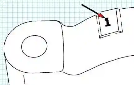
a) Check the presence of alignment marks on the main bearing caps and cylinder block.
The numbering of covers starts from the front of the engine.
b) Loosen the main bearing cap bolts, but do not remove them.
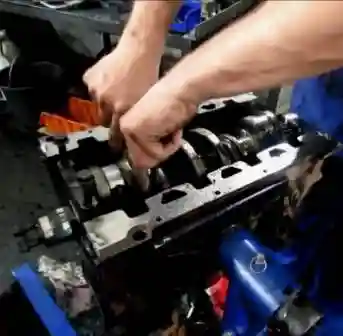
c) Using the 2 bolts as a lever, swing the main bearing cap and remove it.
Do not damage the threads of the bolts.
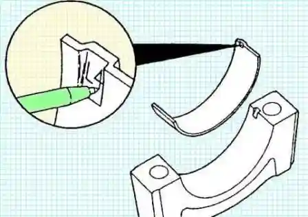
We put marks on the removed parts in accordance with their location
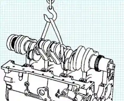
Remove the crankshaft
Remove the upper main bearing shells.
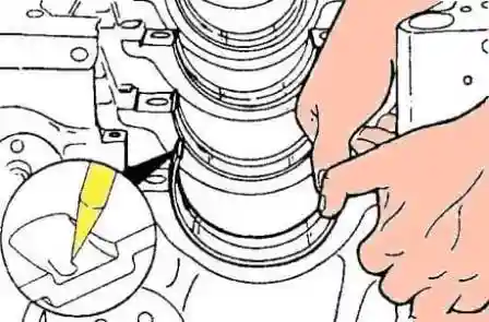
Put a relative position mark on the removed insert
Checking the crankshaft
Measure the diameter of the connecting rod and main journals of the crankshaft.
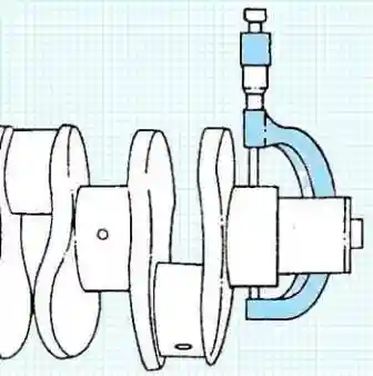
Crankpin diameter:
- - nominal 68.962 - 69.013 mm;
- - repair (0.25 mm) 68.712 - 68.763 mm;
- - repair (0.50 mm) 68.462 - 68.513 mm.
Main journal diameter:
- - nominal 82.962 - 83.013 mm;
- - repair (0.25 mm) 82.712 - 82.763 mm;
- - repair (0.50 mm) 82.462 - 82.513 mm.
Maximum ovality 0.050 mm
Max taper 0.013 mm
If the dimensions of one neck differ from the nominal, bore all the necks to the nearest repair size.
Determine the main bearing clearance with a plastic gauge.
Put the crankshaft into the cylinder block.
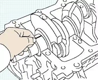
Place a plastic gauge across each main journal.
Install the main bearing caps.
Tighten the main bearing cap bolts.
Note: do not turn the crankshaft.
Remove the crankshaft main bearing caps.
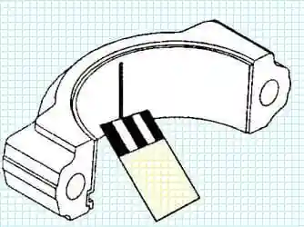
Measure the maximum width of the flattened gauge to determine the radial clearance.
Clearance in the main bearing 0.04 - 0.12 mm
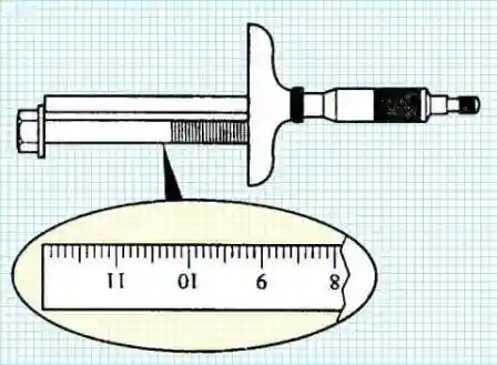
Check the shaft length of the main bearing cap bolt.
Maximum length 120 mm
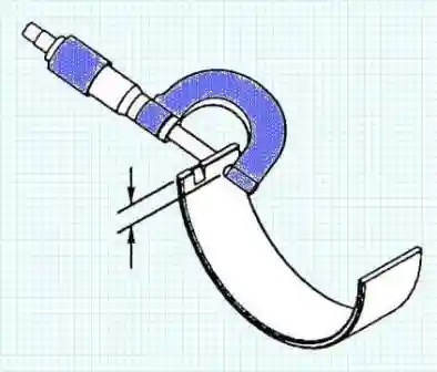
Check the thickness of the main bearing shells.
Insert thickness:
- - nominal 2.456 - 2.464 mm;
- - repair (0.25 mm) 2.706-2.714 mm;
- - repair (0.50 mm) 2.956-2.964 mm.
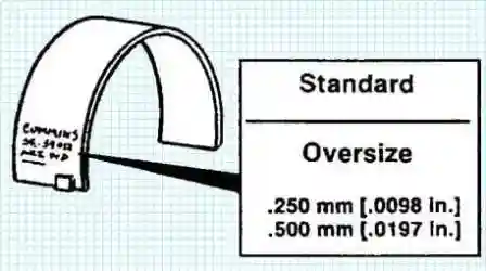
If necessary, select a new bearing according to the number stamped on the back of the old bearing.
Installing the crankshaft
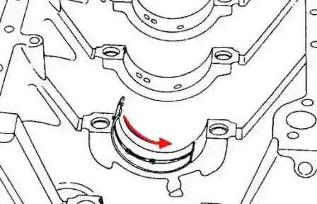
Install the main bearing shells by aligning the protrusions of the shells with the recesses of the main bearing beds.
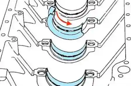
Install the crankshaft thrust bearing shell onto the #4 main bearing.
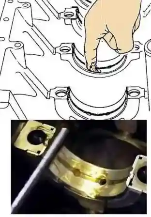
Apply Assembly Grease (#3163O87) to the running surfaces of the main bearings and the crankshaft side thrust bearing.
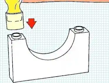
Make sure the guide bushings are in the main bearing caps.
Install the crankshaft.
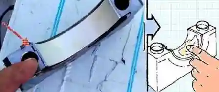
Install the main bearing shells by aligning the protrusions of the shells with the recesses of the main bearing caps
Apply Assembly Grease (#3163087) to the crankshaft side of the main bearing and thrust bearing running surfaces.
Do not apply lubricant to the back of the earbud!
Check that the surfaces of the main bearing caps between the cap and the cylinder block are free of dirt and foreign matter.
Install the main bearing caps according to the numbers marked on removal.
Align the guide bushes on the main bearing cap with the corresponding holes in the cylinder block.
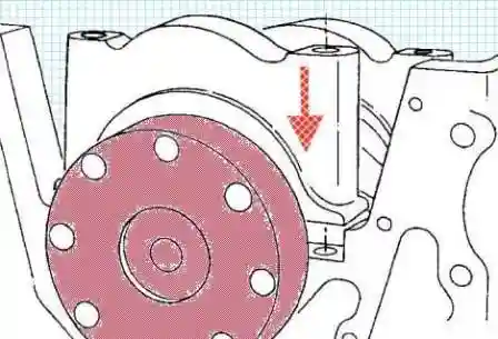
Note: make sure the covers are correctly installed in the places they were removed from, numbered in the direction of the engine oil cooler.
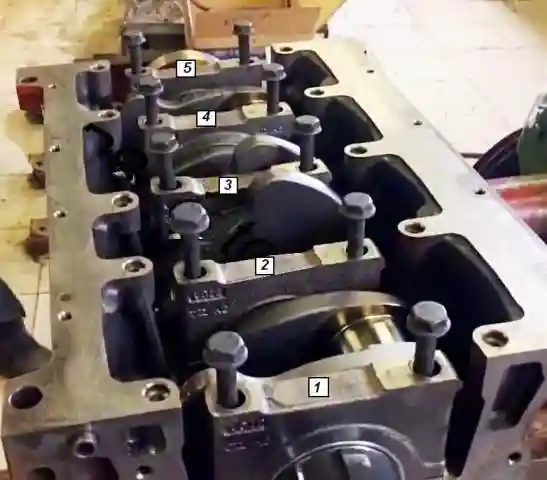
Numbering starts at the front of the engine.
Lubricate the threads and under the bolt heads with engine oil.
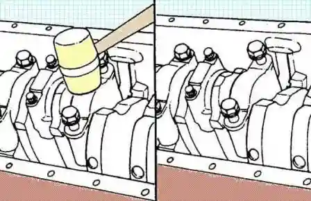
Install the main bearing cap by gently tapping it with a plastic-faced hammer.
After the cover is in place, tighten the bolts.
Tightening torque 50 Nm
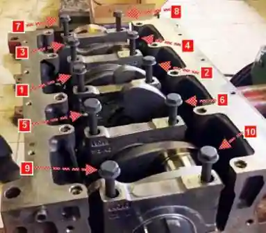
Tighten the bolts evenly in the sequence shown in figure 20.
Perform each operation on all bolts before moving on to the next operation.
Tightening torque:
Used bolts:
- - first stage 60 Nm;
- - second stage 80 Nm;
- - turn the third stage by 90°.
New bolts:
- - first stage 120 Nm;
- - second step completely loosen the bolts;
- - third stage 60 Nm;
- - fourth stage 85 Nm;
- - turn the fifth stage by 120°.
Make sure the crankshaft rotates freely.
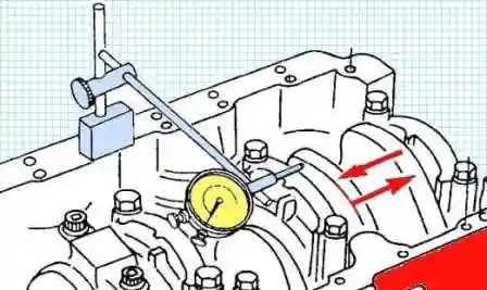
Using a dial indicator, check the axial movement of the crankshaft.
Axial movement 0.11 - 0.39 mm
If the axial clearance is greater than the maximum value, replace the main bearing thrust shell, which is installed in the region of the main journal 4.
There are repair sizes of thrust inserts 0.25 mm and 0.50 mm.


