
The engine cylinder block is cast from cast iron
The casting is subjected to artificial aging to relieve thermal stress, which allows the block to retain the correct geometric shapes and dimensions during operation
Two rows of half-blocks for cylinder liners, cast as a single piece with the upper part of the crankcase, are located at an angle of 90° to each other.
The left row of bores for the liners is offset relative to the right one forward (towards the fan) by 29.5 mm, which is due to the installation of two connecting rods on each crankpin of the crankshaft.
Each bore has two coaxial cylindrical holes made in the upper and lower belts of the block, along which the cylinder liners are centered, and undercuts in the upper belt, forming annular platforms for the flanges of the liners.
To ensure correct fit sleeves in the block, the parameters of flatness and perpendicularity of the thrust pad under the sleeve flange relative to the axis of the centering bores are performed with high accuracy.
Two grooves for sealing rings are made on the lower belt, which prevent coolant from the block cooling cavity from entering the engine oil sump cavity.
The bosses of the holes for the cylinder head mounting bolts are made in the form of lugs to the transverse walls that form the cooling jacket, evenly distributed around each cylinder.
The crankcase part of the block is connected to the main bearing caps with main and tie bolts.
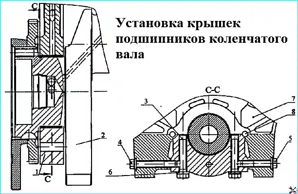
The centering of the main bearing caps is performed by horizontal pins 8 (Figure 1), which are pressed into the joint between the block and the caps, but mostly included in the block to prevent them from falling out when removing the caps.
In addition, the cover of the fifth main support is centered in the longitudinal direction by two vertical pins, ensuring the accuracy of the coincidence of the bores for the crankshaft thrust half rings on the block and on the caps.
The order of tightening the bolts for fastening the main bearing caps in accordance with the article - "Tightening torques for KAMAZ diesel fasteners"
The boring of the cylinder block for the main bearing shells is performed assembled with the caps, therefore the main bearing caps are not interchangeable and are installed in a strictly defined position.
Each cover has a serial number of the support, the numbering of which starts from the front end of the block.
In the crankcase part of the collapse of the cylinder block, the valve tappet guides are made in the form of bosses.
Closer to the rear end between the fourth and eighth cylinders, to improve the circulation of the coolant, a bypass pipe of the cooling cavity is made.
At the same time, it also gives the block additional rigidity.
Parallel to the axis of the bores for the crankshaft bearings, bores for the camshaft bushings of increased size are made.
The diameters of the oil channels in the cylinder block are increased.
In the lower part of the cylinders, bosses for the piston cooling nozzles are cast together with the block.
In order to install a filter with The heat exchanger on the right side has been enlarged compared to the 740.10 engine, the filter platform has been enlarged, two additional mounting holes and a drain hole from the filter have been introduced.
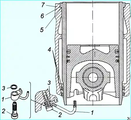
Cylinder liners (Figure 2) "wet" type, easily removable have marking 740.50-1002021 on the conical part at the bottom of the liner.
Installation of liners with other markings is unacceptable due to the resulting contact with the connecting rod.
The 740.50-360 and 740.51-320 engine liners are 3 mm lower in height than the liners of other KAMAZ engine models with dimensions 120x120.
The cylinder liner is made of special gray cast iron strengthened by bulk hardening.
At the liner - cylinder block connection, the cooling cavity is sealed with rubber rings of circular cross section.
At the top, ring 5 in the groove of the sleeve, in the lower part - two rings 4 in the bore of the cylinder block.
Microrelief on The sleeve mirror is a sparse grid of depressions and platforms with small risks at an angle to the sleeve axis.
When the engine is running, the oil is retained in the depressions, which improves the running-in of the cylinder-piston group parts.
When the engine is assembled, the cylinder number and piston version index are applied to the non-working projection of the sleeve end.
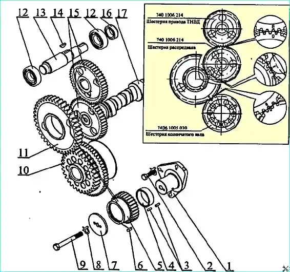
The drive of the units (Figure 3) is carried out by spur gears and serves to drive the valve timing mechanism, high-pressure fuel pump, compressor and power steering pump of the car.
The valve timing mechanism is driven by gear 10 mounted on the crankshaft tailstock, through a block of intermediate gears that rotate on two rows of rollers 3 separated by an intermediate sleeve 4 and located on an axis 1 fixed to the rear end of the cylinder block.
A gear is pressed onto the end of the camshaft, the angular position of which relative to the shaft cams is determined by a key.
Gear 15 of the high-pressure fuel pump (HPFP) drive is mounted on shaft 13 of the HPFP drive and is fixed with key 14.
The gears are installed on the engine in a strictly defined position according to the mark "0" on the camshaft drive gear, the mark "E" on the fuel injection pump drive gear and the risks stamped on the gear wheels, as shown in Figure 3.
The fuel injection pump is driven by gear 15, which is in engagement with the camshaft gear.
Rotation from the shaft to the fuel injection pump is transmitted through the leading and driven half couplings with elastic plates, which compensate for the misalignment of the fuel injection pump shafts and gear.
The compressor and power steering pump drive gears are in engagement with the fuel injection pump drive gear.
The crankcase of the units is attached to the rear end of the cylinder block. In the upper part of the crankcase there are bores in which the compressor and power steering pump are installed.
On the sides of the crankcase there are bosses with holes for draining oil from the turbochargers and a hole for the oil level indicator.
The drive of the units is closed by the flywheel housing, fixed to the rear end of the cylinder block through the crankcase.
On the flywheel housing on the right there is a place for installing the flywheel lock, used to set the fuel injection advance angle and adjust the thermal clearances in the valve timing mechanism.
The lock handle must be in the upper position when the engine is running.
It is moved to the lower position during adjustment work, in which case the lock is engaged with the flywheel.
In the upper part of the flywheel housing there is a bore in which the rear bearing.
At the bottom of the left side of the crankcase there is a bore in which the starter is installed. In the middle of the crankcase there is a bore for the crankshaft seal.
A lug is made in the upper part of the crankcase on the left, designed for installing the power take-off (PTO). In the absence of a PTO, the inner surfaces of the lug are not processed.
The rear flange of the flywheel housing is made with connection dimensions according to SAE1.

")
")
")
")
")
")
")
")