
After disassembling the block head, rinse all parts in gasoline, wipe and dry.
Clean the combustion chambers from soot.
Inspect the block head. If there are cracks on the jumpers between the valve seats or on the walls of the combustion chambers, traces of burnout, replace the block head.
Check with a metal ruler and feeler gauges if the flatness of the surface of the head adjacent to the block is broken.
To do this, put the ruler with an edge on the surface of the head, in the middle along, and then across and measure the gap between the plane of the head and the ruler with feelers.
If the gap exceeds 0.1 mm, replace the head.
Inspect the valves. If cracks, warping of the valve head, burnout, deformation of the valve stem are found on the working chamfer of the valve, replace the valve.
Minor scratches and scratches on the valve face can be removed by lapping.
For the procedure for grinding valves, see the article - “Disassembly and assembly of the cylinder head”.
Check the condition of the valve springs. Replace bent, broken or cracked springs.
Check the condition of the valve seats. Seat edges must be free of wear, pitting, corrosion, etc.
Minor damage (minor scratches, scratches, etc.) can be removed by lapping the valves. More significant defects are eliminated by grinding.
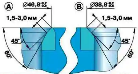
When grinding, keep the dimensions of the saddle shown in the figure.
After grinding, check the runout of the chamfer of the seat against the hole in the valve guide, the maximum allowable runout is 0.05 mm.
After grinding the seats, grind the valves.
Then, thoroughly clean and blow out the head of the block with compressed air so that no abrasive particles remain in the channels closed by the valves and in the combustion chambers.
Check clearance between guide bushings and valves.
Clearance is calculated as the difference between the diameter of the bore in the sleeve and the diameter of the valve stem.
The maximum allowable gap is 0.25 mm.
If the gap exceeds the specified value, the valve and guide sleeve must be replaced.
The old bushing is pressed out with a mandrel from the side of the combustion chamber.
Before installation, new bushings must be cooled in carbon dioxide ("dry ice"), and the block head must be heated to 160-175 ° C.
Then insert the sleeve into the block head so that it protrudes from the side of the valve springs above the block head by 20 mm.
The sleeve should be inserted into the head freely or with little effort. After installation, ream the hole in the sleeve to a diameter of 9.0+0.022 mm.
Then grind the valve seat, centering the tool over the hole in the sleeve.
You can check the block head for cracks as follows. Connect a compressed air hose to one of the holes in the cooling jacket.
Plug all holes in the block head with wooden plugs. Immerse the head in a bath of water and apply compressed air at a pressure of 1.5 atm.
Air bubbles will come out in places where cracks form.
Clean with wire and blow out with compressed air the holes in the axis of the rocker arms, in the rocker arms and in the adjusting screws.
Check the tightness of the bushings in the rocker arms.
If the bushing is not tight, it must be replaced, as during engine operation it can turn and block the hole for supplying oil to the pusher rod.
Cylinder head dimensions and fittings are shown in the tables.
Nominal cylinder head dimensions

Fitting the mating parts of the cylinder head
