We conditionally remove the gear and the oil pump drive roller from the engine dismantled from the car.
To remove the oil pump drive gear, unscrew the generator mounting bracket (article - engine disassembly).
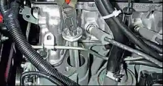
Having grasped the rib of the oil pump drive gear retainer with pliers, we remove the retainer from the cylinder block socket.
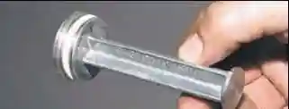
The connection is sealed with a rubber ring, put on the head of the latch.
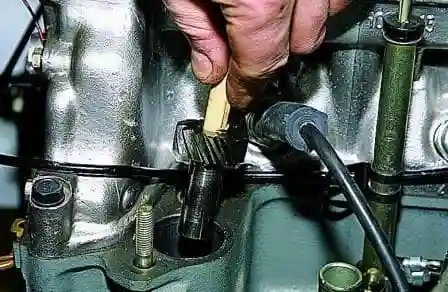
We insert a wooden cone with an interference fit into the splined hole of the oil pump drive gear and remove the gear from the cylinder block by turning it counterclockwise.
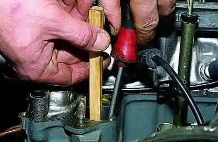
When installing the gear, we put it on the splined shank of the oil pump roller and engage it with the gear of the oil pump drive roller, holding the gear with a screwdriver, remove the wooden mandrel
To remove the oil pump drive shaft you need to remove:
- - auxiliary drive pulley;
- - timing cover;
- - timing chain.
Remove the oil pump drive gear from the cylinder block.
Remove the oil pump drive sprocket for this:
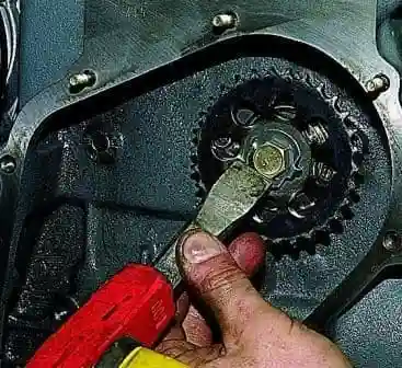
With a chisel or screwdriver, bend the lock washer of the sprocket bolt
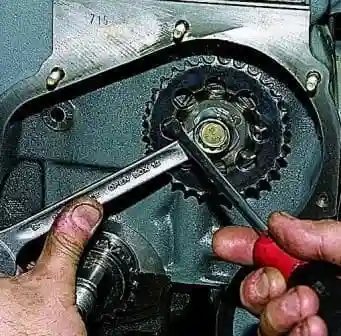
Use a 17 key to unscrew the sprocket mounting bolt.
We hold the sprocket from turning with a screwdriver resting through the hole in the sprocket on the head of the bolt securing the roller thrust flange.
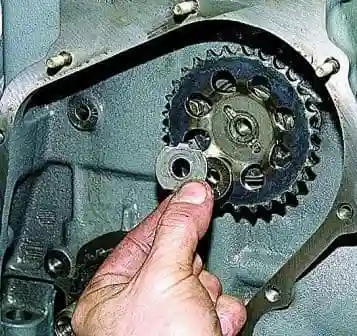
Removing the bolt with washers
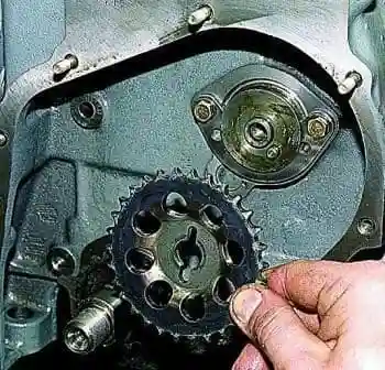
Remove the star
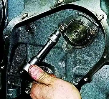
With a “10” head, we unscrew the two bolts securing the roller thrust flange to the cylinder block and remove the thrust flange
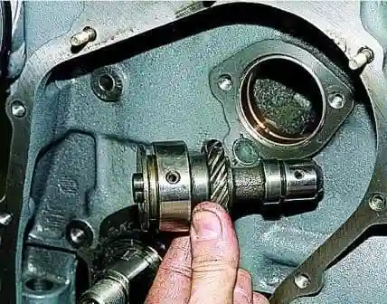
Remove the oil pump drive roller from the cylinder block socket
Defection of the roller and gear of the oil pump drive
There should be no dents or scratches on the surfaces of the bearing necks of the roller and on the working surface of the eccentric.
On the teeth of the oil drive gearsth pump and ignition distributor are not allowed to chip, with such a defect, replace the gears and roller with new ones.
Oil pump drive shaft bushings.
Check the inner diameter of the bushings, their pressing into the sockets, as well as the coincidence of the lubrication hole in the front bushing with the channel in the cylinder block (turning the bushing).
The inside surface must be smooth and free of burrs.
Having measured the diameters of the roller and bushings, determine the gaps between the bushings and the supporting surfaces of the roller.
If the gap exceeds 0.15 mm (wear limit), as well as if the surfaces of the bushings are damaged or their pressing is weakened, replace the bushings with new ones.
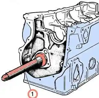
When replacing, use tool A.60333/1/2 for both removal and installation, observing the following:
- the bushings must be pressed into the sockets, while the oil hole in the front bushing must be against the channel in the cylinder block;
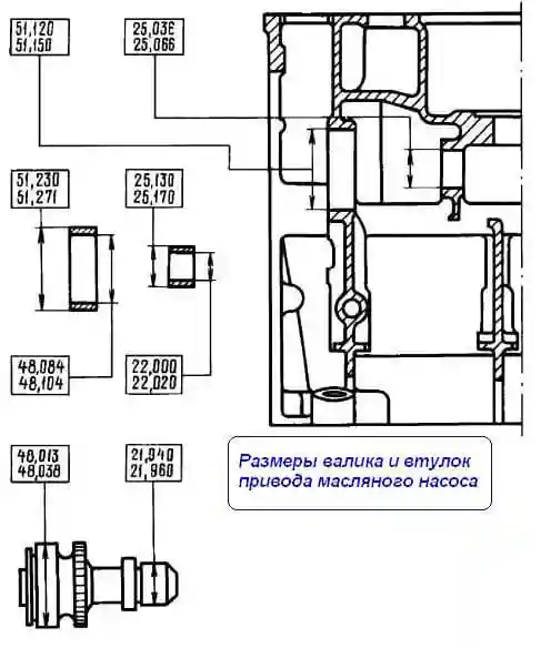
- after pressing in, the bushings must be finished and finished on the inner diameter (dimensions are given in the figure).
To ensure complete alignment of the roller bushings, a reamer A.90353 is used to finish them, which simultaneously processes both bushings.
Oil pump drive gear bushing
Check the bushing is pressed in. The inner surface must be smooth and without scratches, otherwise replace the sleeve.
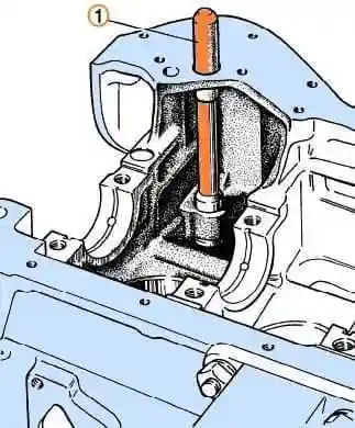
To press out and press in the bushing, use the mandrel А.60З26 / I.
After pressing the bushing, process it with a reamer up to 16.016-16.037 mm.
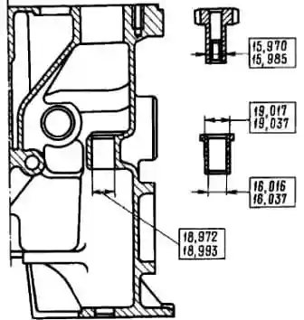
Install the oil pump drive shaft in reverse order.
Further assembly is carried out in the reverse order.
We replace the rubber ring of the retainer with a new one if it is torn or has lost its elasticity.


